
Ultrasonic Pulse Echo Defectoscopy and Concrete Imaging (Ultrasonic Echo Tomography)
During production quality control and acceptance testing of cast-in-place and precast-cast-in-place concrete and reinforced concrete structures, the following tasks are frequently required:
— Determination of geometric characteristics, including thickness of monolithic reinforced concrete foundation slabs and grade beams, basement walls, retaining walls, and diaphragm walls, including under single-sided access conditions;
— Detection of cold joints (delaminations, inclined layering) in monolithic reinforced concrete foundation slabs, grade beams, basement walls, retaining walls, and diaphragm walls, even when only single-sided access is available;
— Identification of concealed internal defects in concrete, such as cracks, voids, cavities, and zones of insufficient compaction in monolithic reinforced concrete foundation slabs, grade beams, walls, piers, columns, floor slabs, and roof slabs, including under single-sided access;
— Localization of reinforcement elements within reinforced concrete members (vertical and horizontal main rebars in piers and columns; upper and lower rebar mats in slabs) and determination of reinforcement parameters (spacing, concrete cover depth, number of reinforcement layers);
— Provision of technical support and assistance during acceptance inspections of completed monolithic concrete and reinforced concrete structures in compliance with Working Documentation (WD) and applicable regulatory standards;
— Minimization of destructive interventions, such as chipping for concrete cover verification or core sampling for internal structural assessment during technical inspections of concrete and reinforced concrete elements of buildings and structures.
These non-destructive evaluation (NDE) procedures are performed using advanced ultrasonic echo tomography systems that enable high-resolution imaging of internal structural features without compromising the integrity of the inspected elements.
The method is particularly effective where conventional access is restricted to one side of the structure, a common scenario in underground construction, retrofitting projects, or operational facilities.
By integrating ultrasonic pulse echo data with digital signal processing and 3D visualization algorithms, our specialists deliver precise, reliable, and actionable insights into the condition, geometry, and reinforcement layout of critical structural components, ensuring compliance with design specifications and enhancing the safety and durability of constructed assets.
METHOD
Non-destructive testing (NDT) and internal inspection of concrete and reinforced concrete structures under single-sided access achieve the highest reliability when results are presented in a tomographic format. In practice, this is implemented using the ultrasonic pulse-echo method with Synthetic Aperture Focusing Technique combined with Combinational Scanning (SAFT-C).
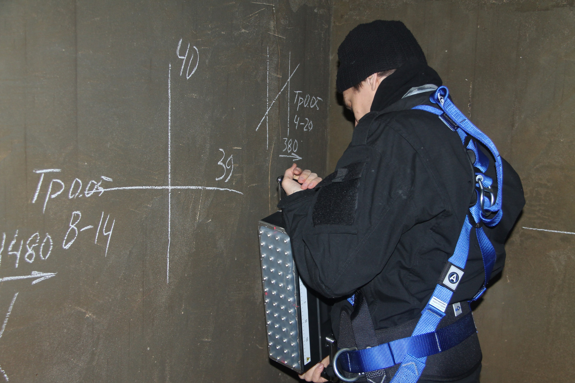
For this purpose, the surface of the structure is scanned using a matrix array of ultrasonic transducers. The best performance characteristics are delivered by equipment employing dry-point-contact transducers with transverse shear-wave motion. The output of scanning a section of a reinforced concrete surface is a three-dimensional data array that, when processed with specialized software, enables the reconstruction of a 3D image of the scanned structural segment.
This visualization clearly depicts the spatial configuration of the embedded reinforcement system and allows for cross-sectional views of the segment in three mutually perpendicular planes.
Furthermore, ultrasonic echo tomography facilitates the detection of internal concrete defects within the scanned area, such as voids, delaminated zones, and other discontinuities in the concrete matrix.
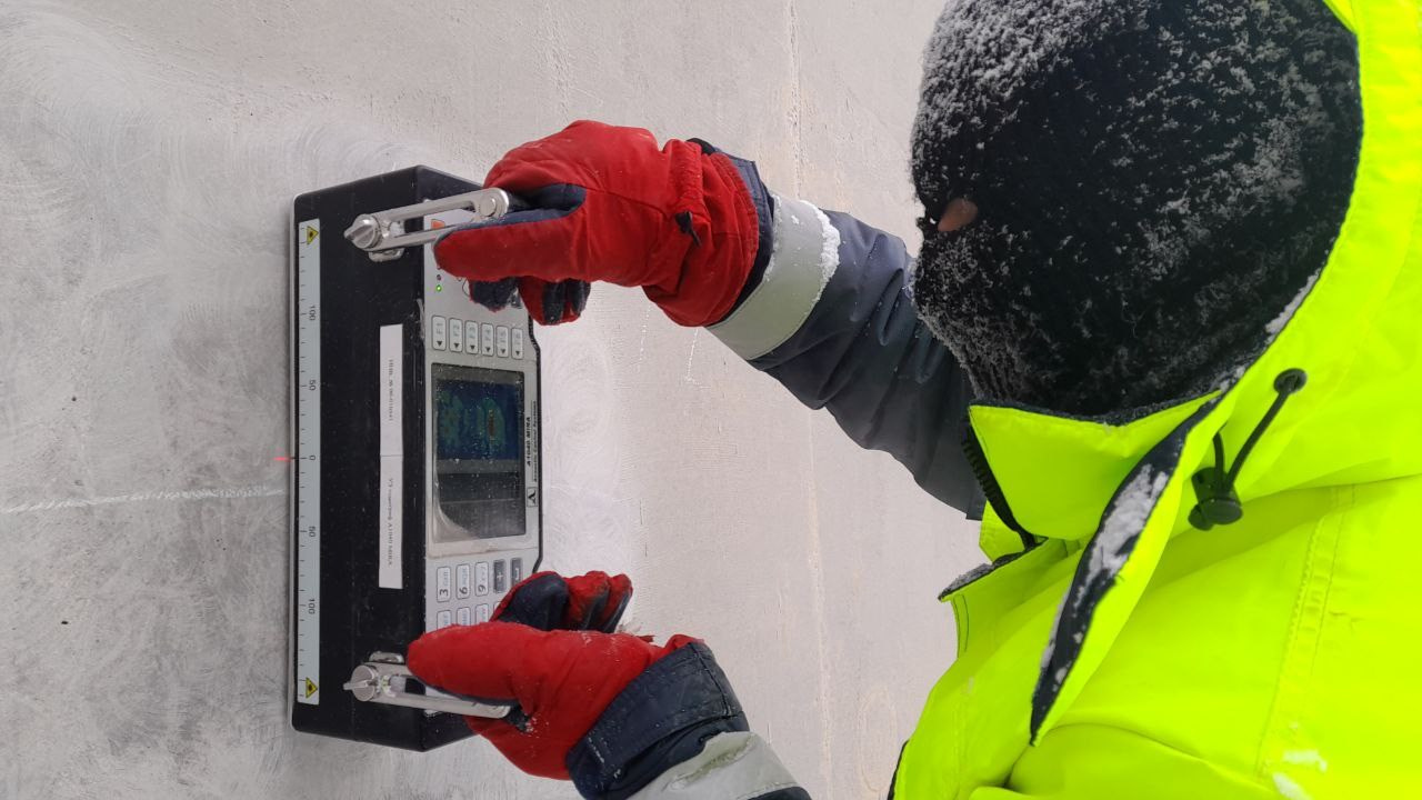
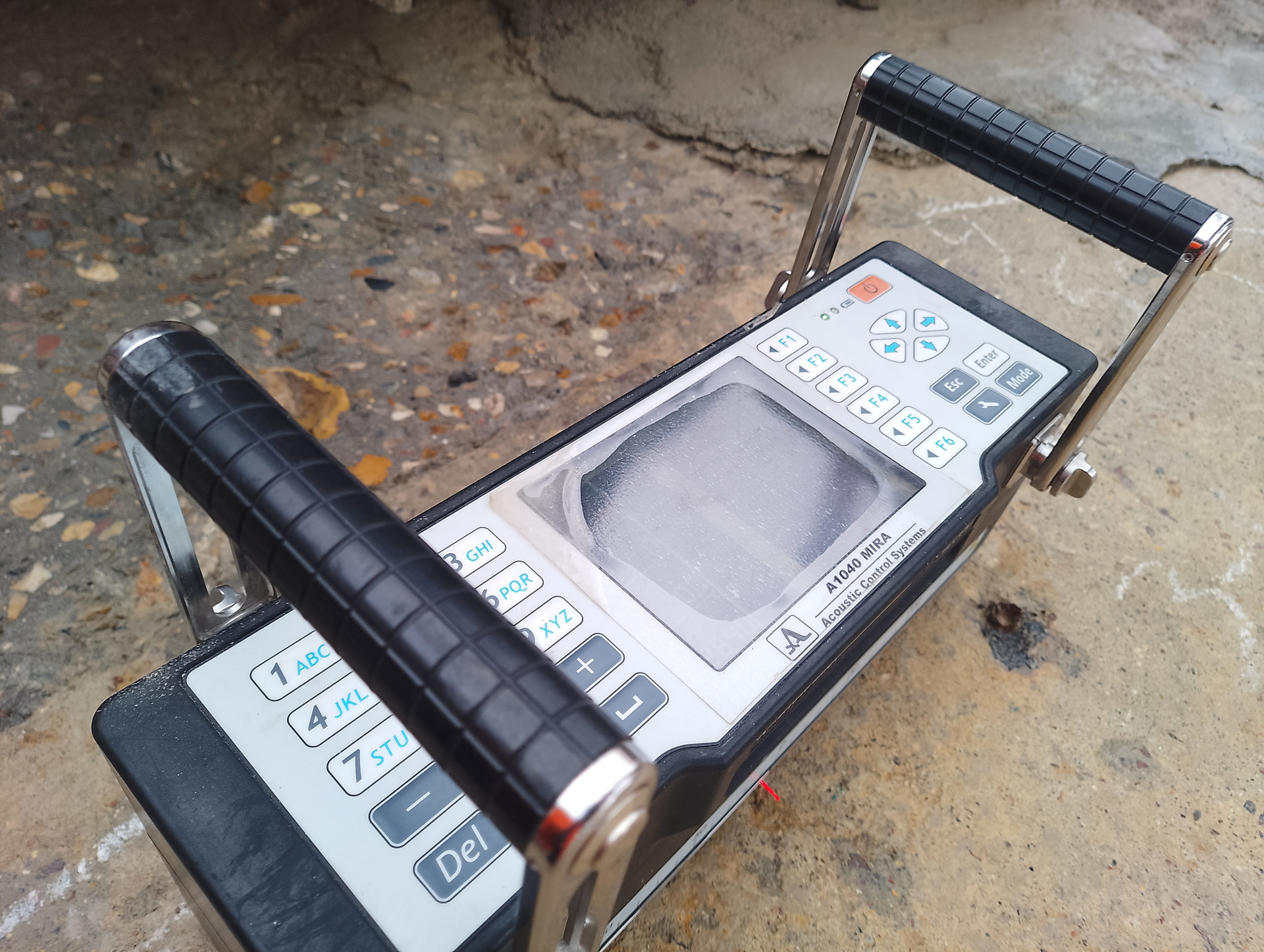
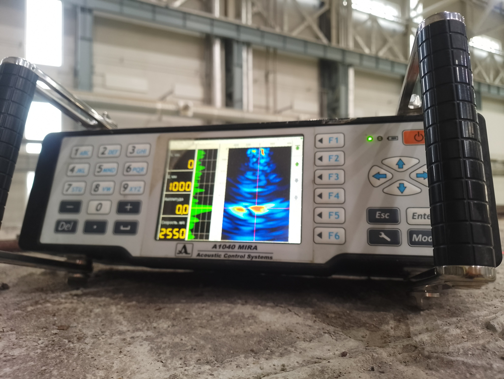
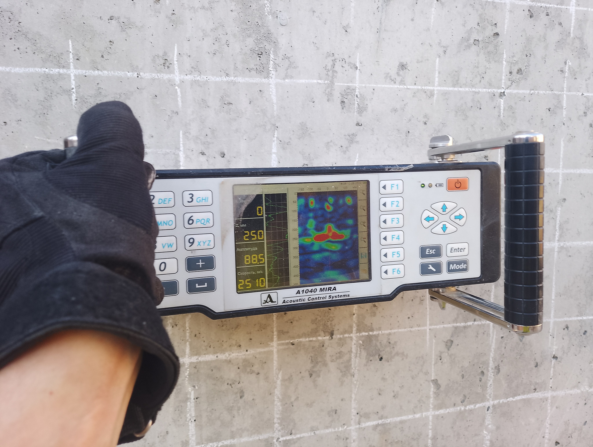
EQUIPMENT
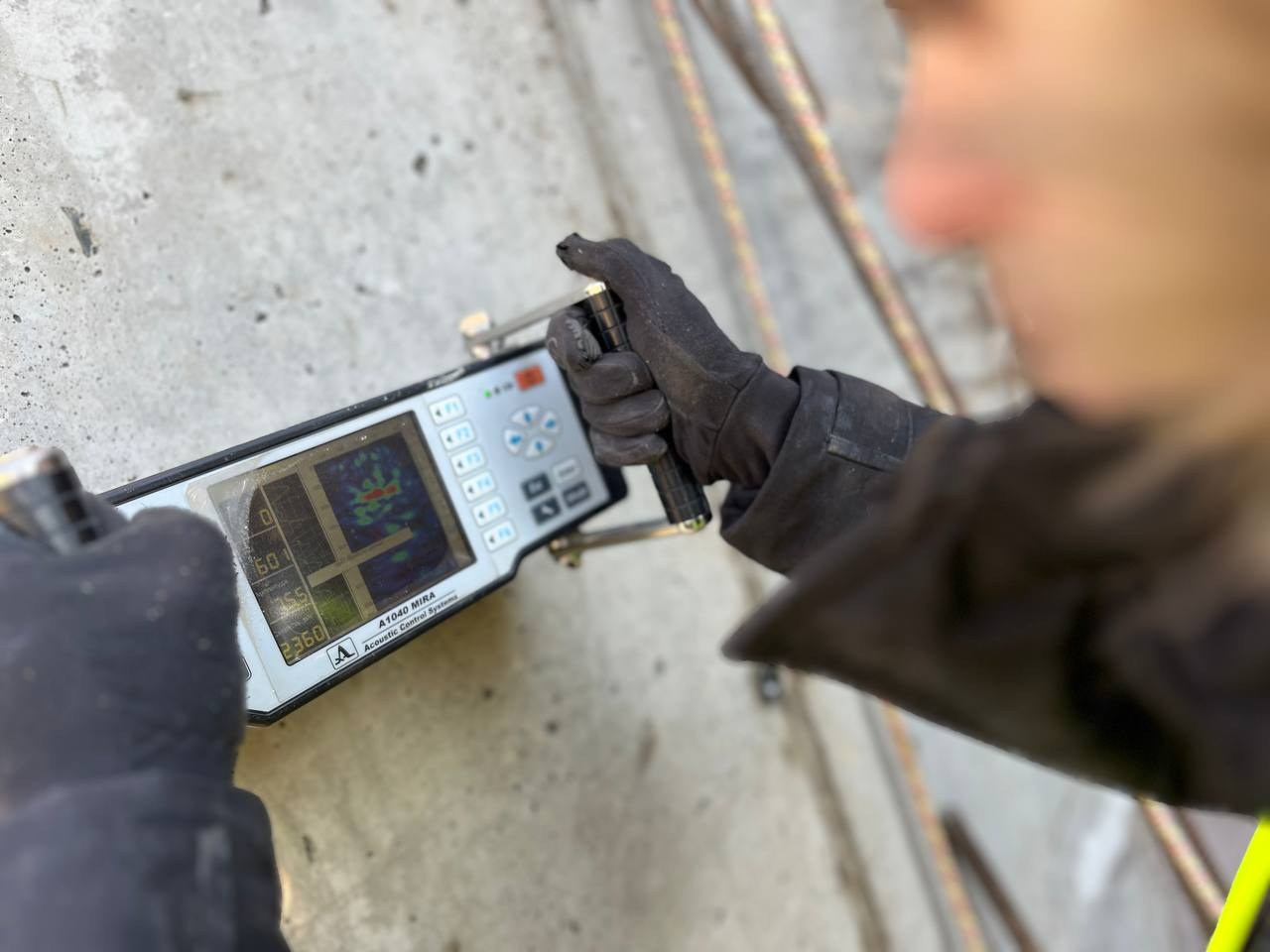
The application of low-frequency ultrasonic tomographs, such as the A1040 MIRA and A1040 MIRA 3D units manufactured by ACS (Russia), and the A1220 Monolith flaw detector enables accurate determination of reinforced concrete reinforcement parameters (including rebar spacing and concrete cover depth) as well as geometric characteristics of structural elements, even under single-sided access conditions.
This approach significantly reduces the required number of exploratory openings or eliminates the need for them altogether.
Moreover, in certain cases, exploratory openings either fail to provide complete information on all reinforcement parameters or are physically impossible to execute due to structural, operational, or safety constraints.
When used as a supplementary tool during verification openings, the A1040 MIRA tomograph allows for efficient validation of reinforcement parameters against the requirements of SP 70.13 330 while minimizing the number and extent of structural penetrations, thereby reducing damage to the structure to the greatest possible extent.
WORK RESULTS
The outcome of non-destructive testing and internal inspection of concrete and reinforced concrete structures performed by the ultrasonic pulse-echo method (ultrasonic echo tomography) is a formal «Inspection Report (Conclusion) on the Results of Ultrasonic Pulse-Echo Testing and Internal Examination of Concrete and Reinforced Concrete Structures (Ultrasonic Echo Tomography Method)», accompanied by the necessary findings and recommendations.

Example Application of the Method for Determining Reinforcement Cage Layout and Reinforcement Parameters (Number of Layers, Bar Spacing, Concrete Cover Thickness) in a Roof Slab
The capabilities of ultrasonic echo tomography are illustrated below by means of an example involving the determination of reinforcement cage geometry and key reinforcement parameters, including the number of layers, bar spacing, and concrete cover thickness in a 400 mm thick roof slab, assessed via single-sided scanning from the top surface of the slab.
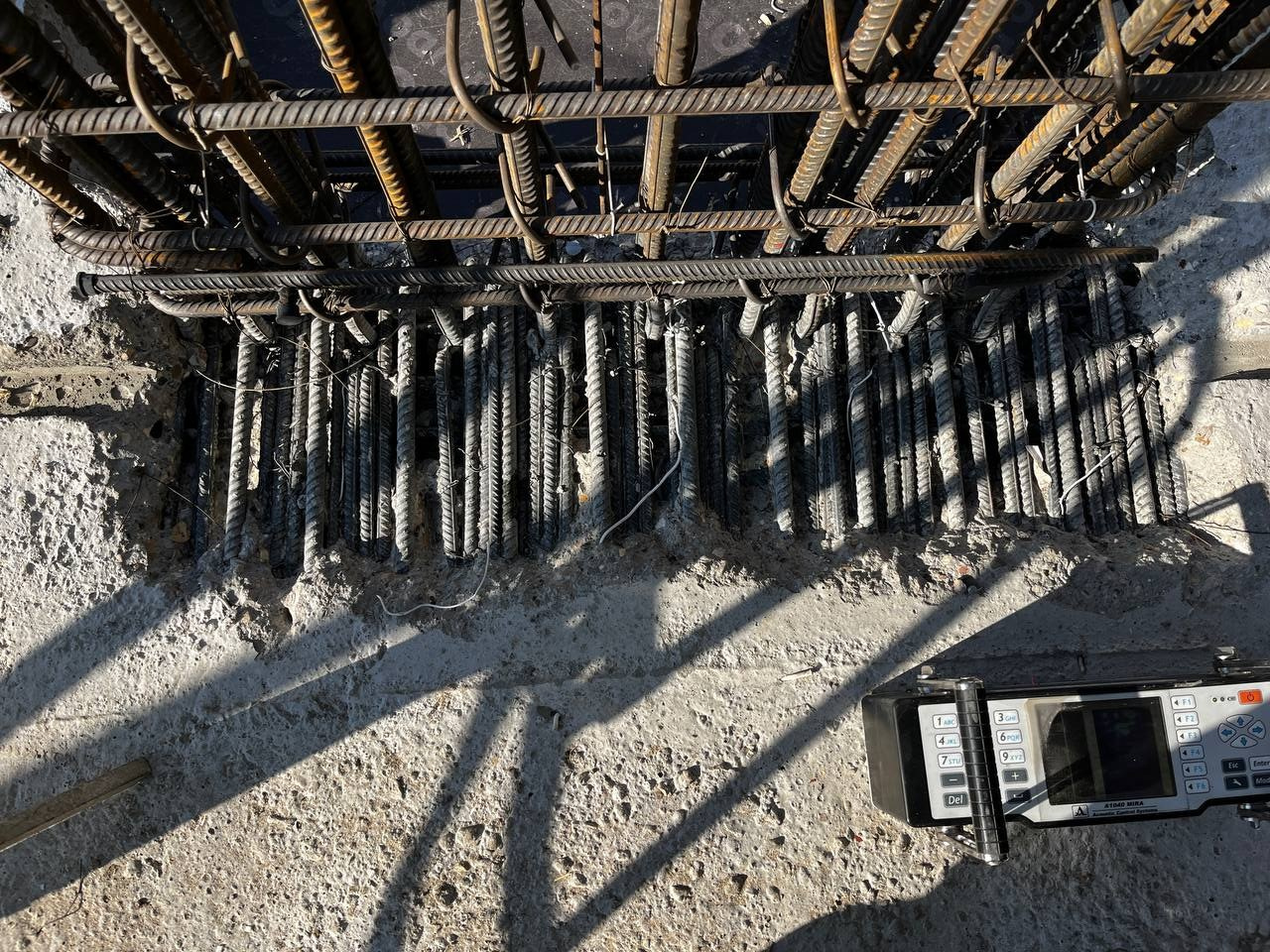
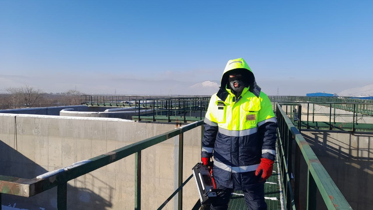
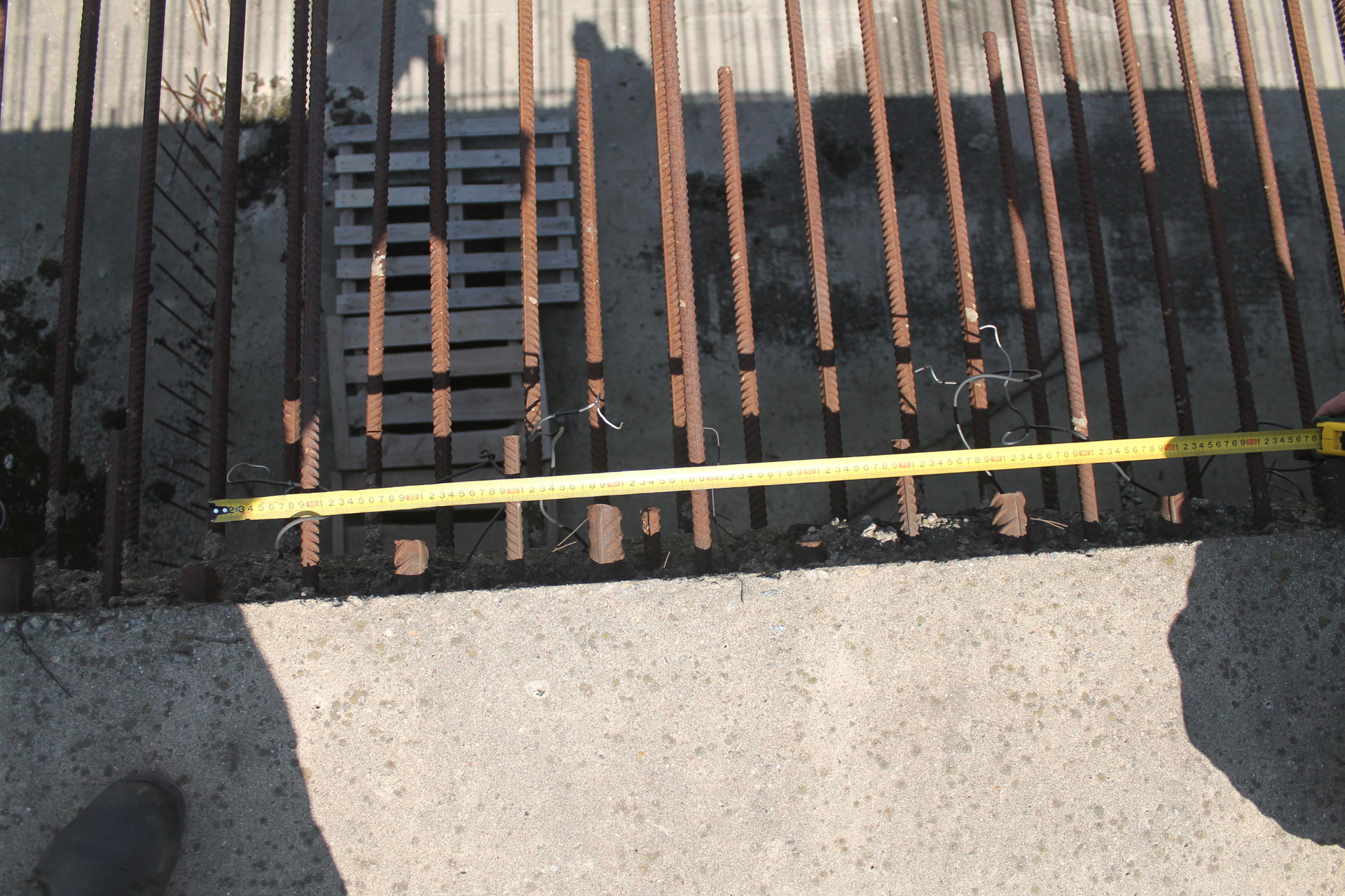
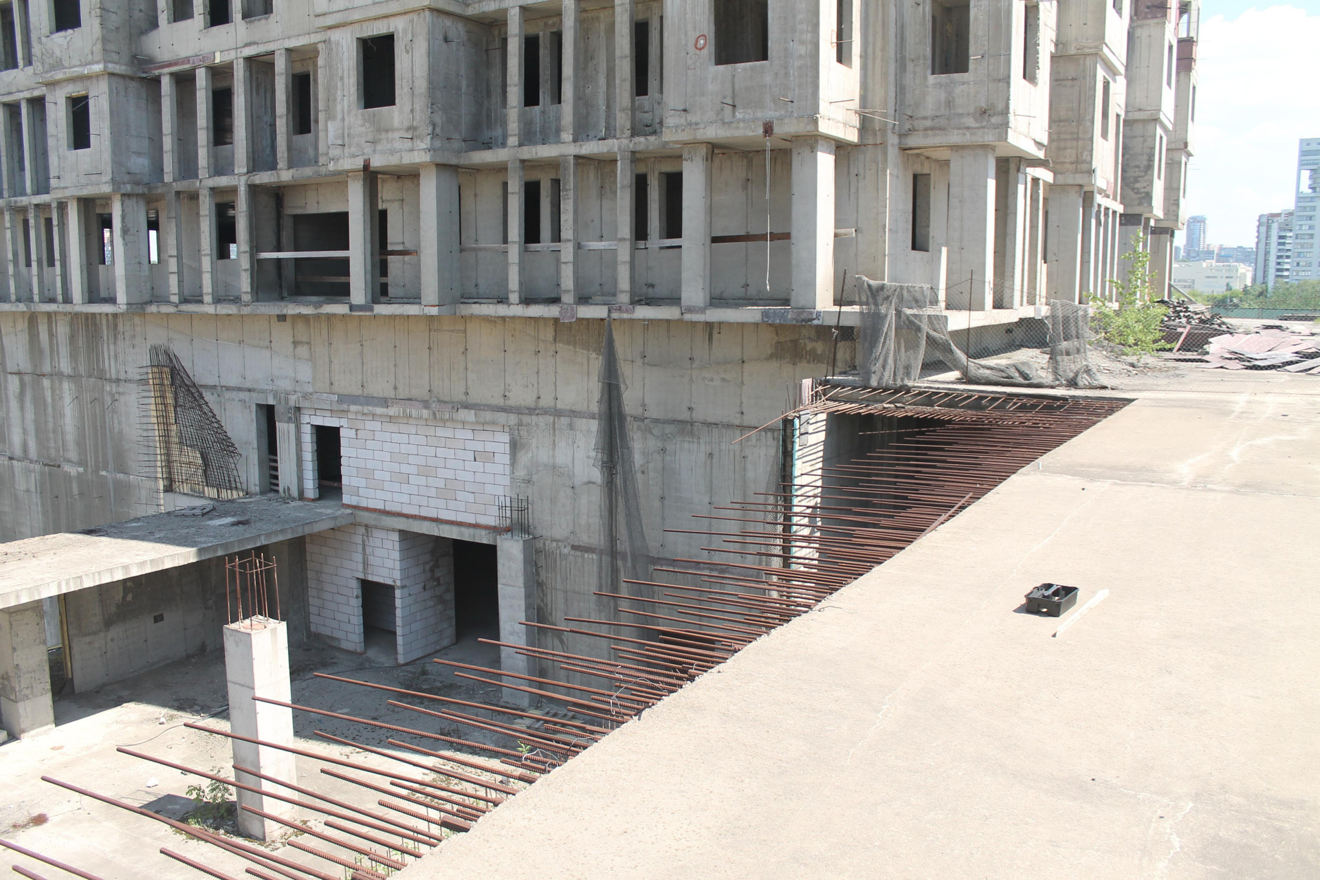
The photographs below show a roof slab located in the stylobate section of an unfinished construction project.
The slab has a total thickness of 400 mm and features four layers of primary reinforcement: two layers adjacent to the top surface and two layers adjacent to the bottom surface.
— At the top surface, the reinforcement bars are spaced at 200 mm intervals in two mutually perpendicular directions.
— At the bottom surface, the reinforcement bars are spaced at 100 mm intervals, also in two mutually perpendicular directions.
— The nominal concrete cover thickness at the top surface is 50 mm.
— The design compressive strength class of the slab concrete is B30.
As a result of scanning a 1000 × 1000 mm area of the roof slab in two mutually perpendicular directions, three-dimensional images of the scanned slab segment were obtained, along with representative cross-sections in three mutually perpendicular planes.
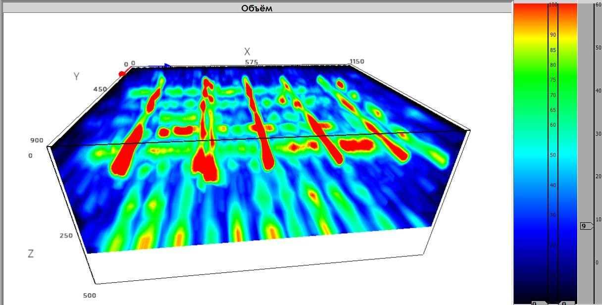
The photographs below show the 3D reconstructions of the roof slab segment within the scanned area.
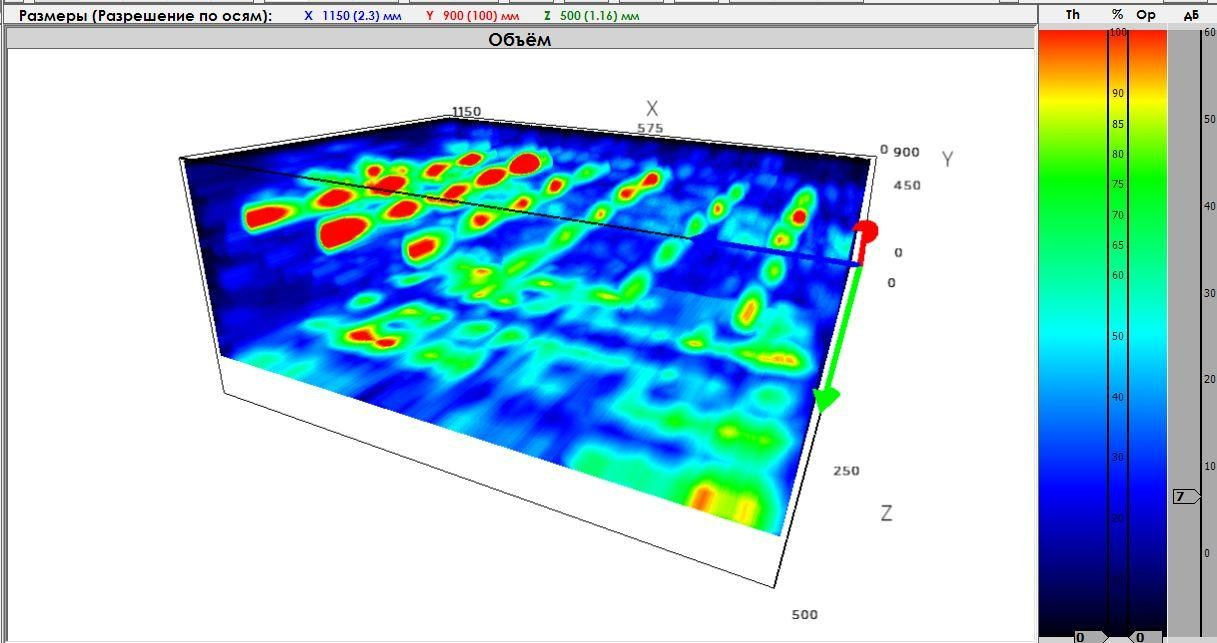
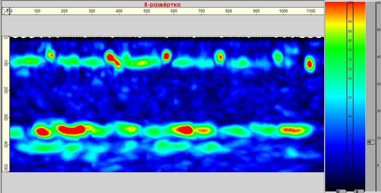
In the cross-sections, a bottom (back-wall) echo signal is clearly detected at a depth of 400 mm, confirming the actual thickness of the structural element. Additionally, the images of the first and second reinforcement layers adjacent to the top surface of the slab are clearly resolved, enabling accurate determination of both the rebar spacing and the concrete cover thickness.
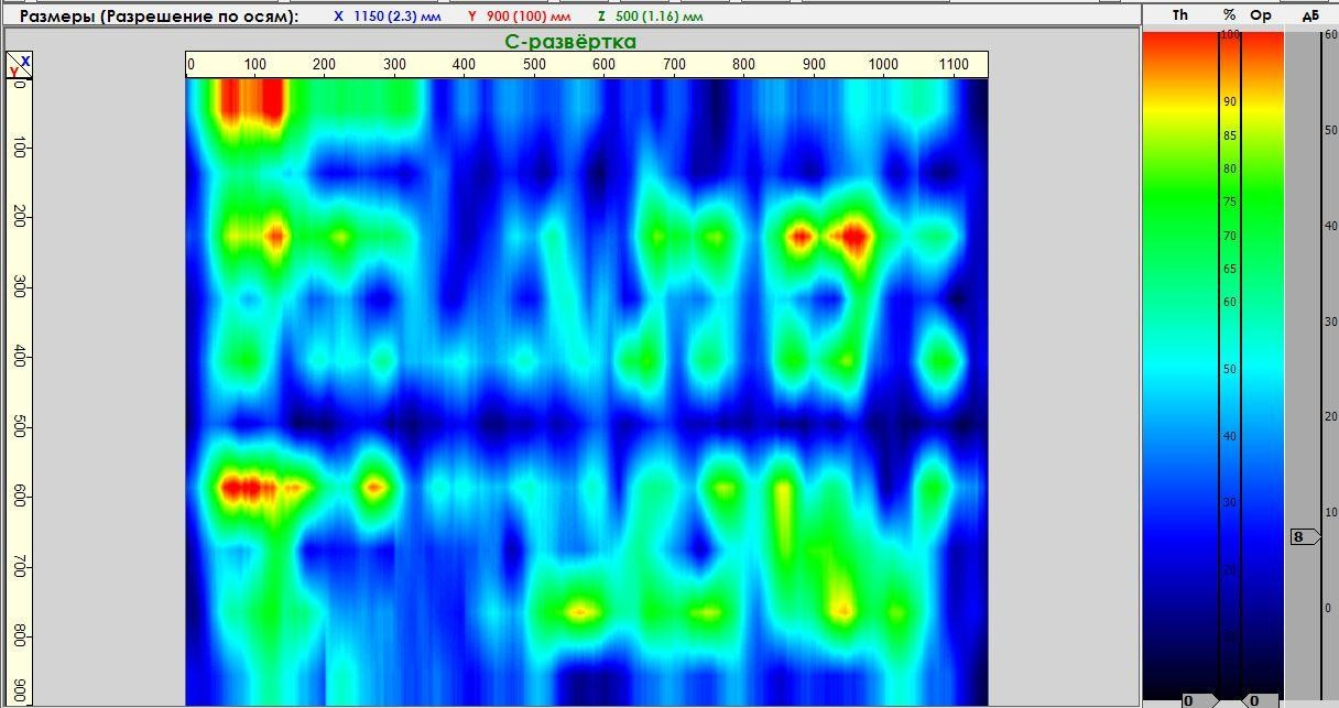
The photographs below illustrate cross-sectional views (B-scan tomograms) of the reinforced concrete structural segment.
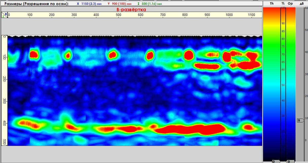
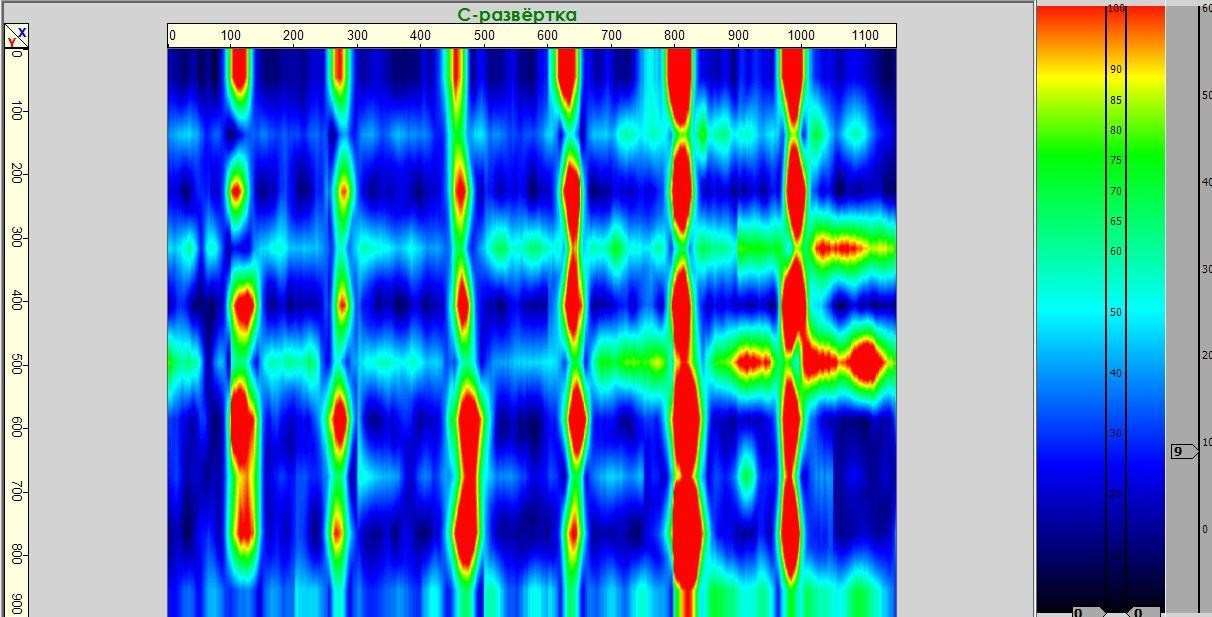
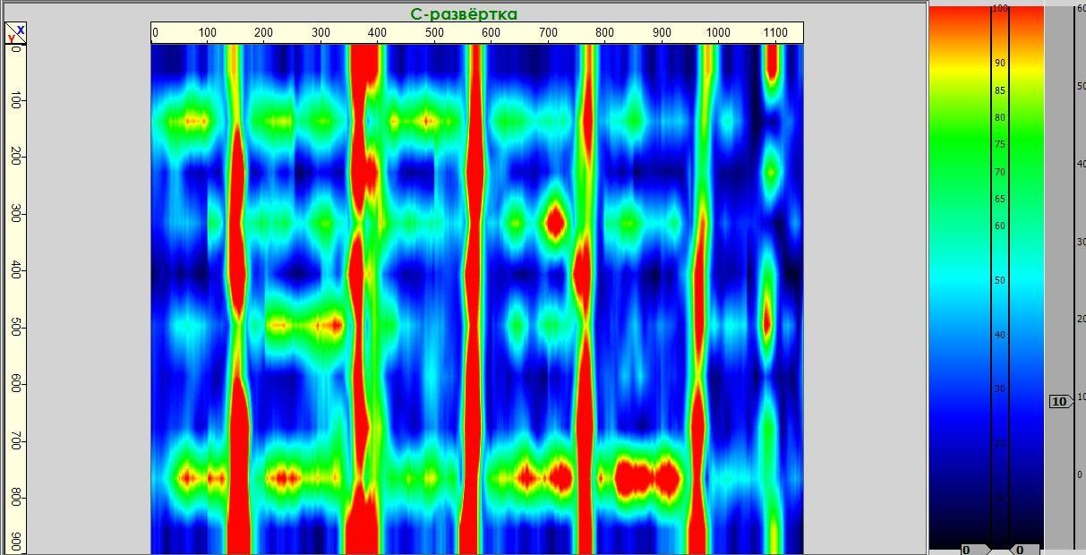
The photographs below show horizontal cross-sections (C-scan tomograms) near the top surface of the reinforced concrete structural segment.
The images clearly reveal the first and second layers of reinforcement adjacent to the top surface of the slab in two mutually perpendicular directions, allowing for accurate determination of both the rebar spacing and the concrete cover thickness.
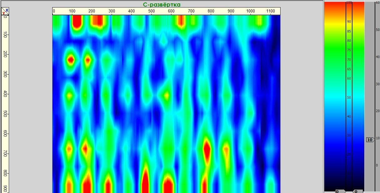
The photographs below show horizontal cross-sections (C-scan maps) near the bottom surface of the reinforced concrete structural segment. The third and fourth reinforcement layers are clearly resolved as distinct images, enabling accurate determination of both the rebar spacing at the bottom surface of the slab and the thickness of the lower concrete cover.
When scanning this area from the underside of the roof slab, B-scan tomograms of the region would be obtained, featuring clear images of the reinforcing bars in the third and fourth layers. These allow precise measurement of the bottom reinforcement spacing in two mutually perpendicular directions.
Thus, the application of ultrasonic echo tomography enables the determination of reinforcement bar locations and actual reinforcement parameters within the scanned area without the need for exploratory openings.
Examples of the Method Applied in Ultrasonic Testing and Internal Inspection of Reinforced Concrete Structures
In the following practical examples of ultrasonic pulse-echo testing (ultrasonic echo tomography), we evaluate the method’s capability to detect artificially introduced internal defects:
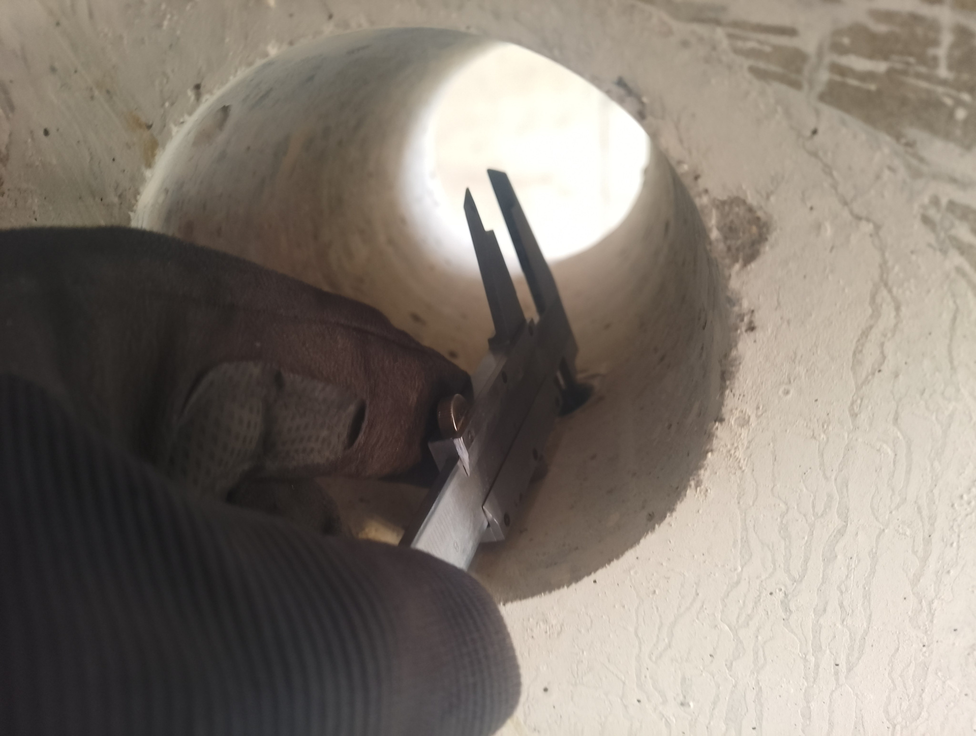
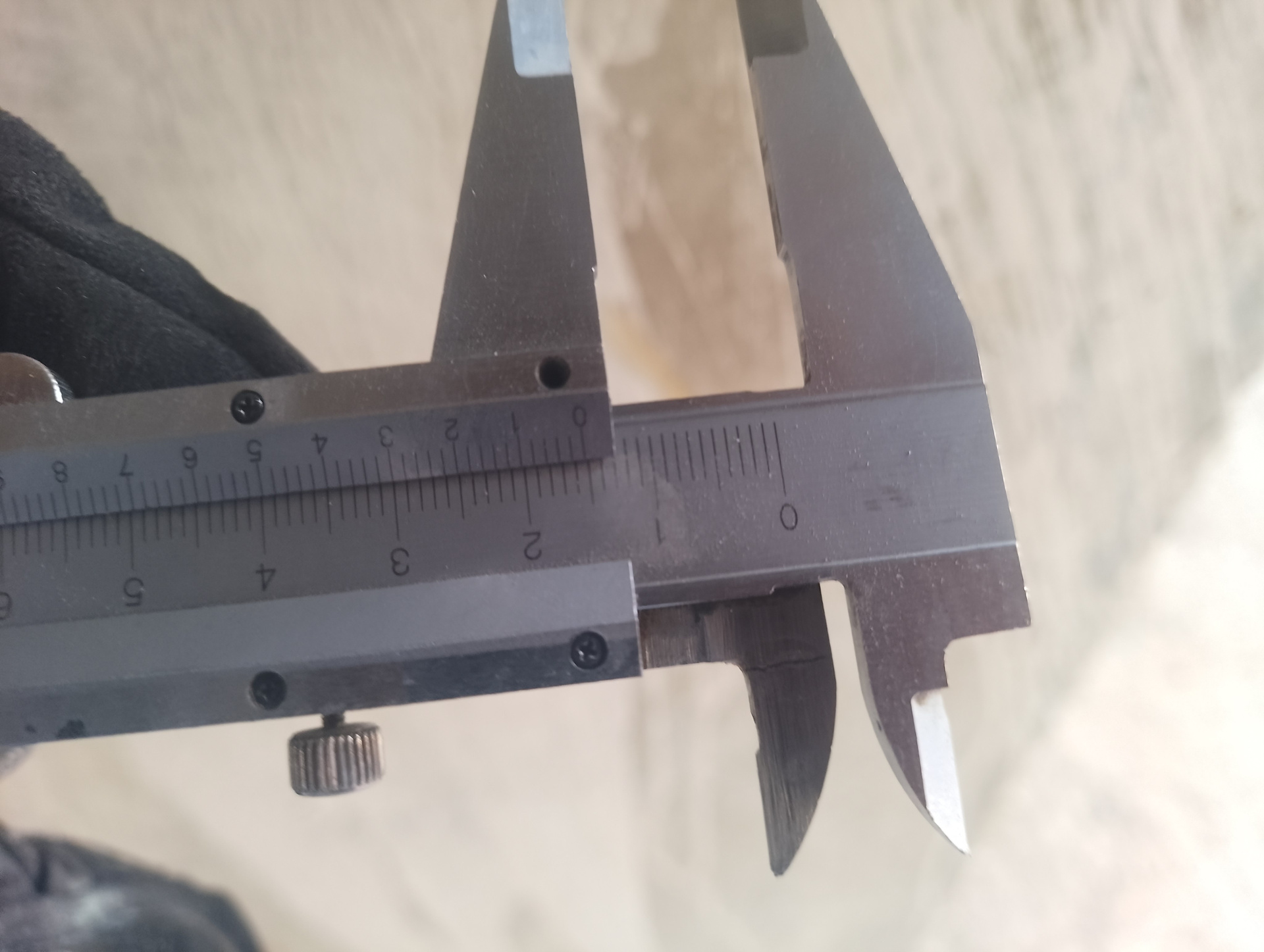
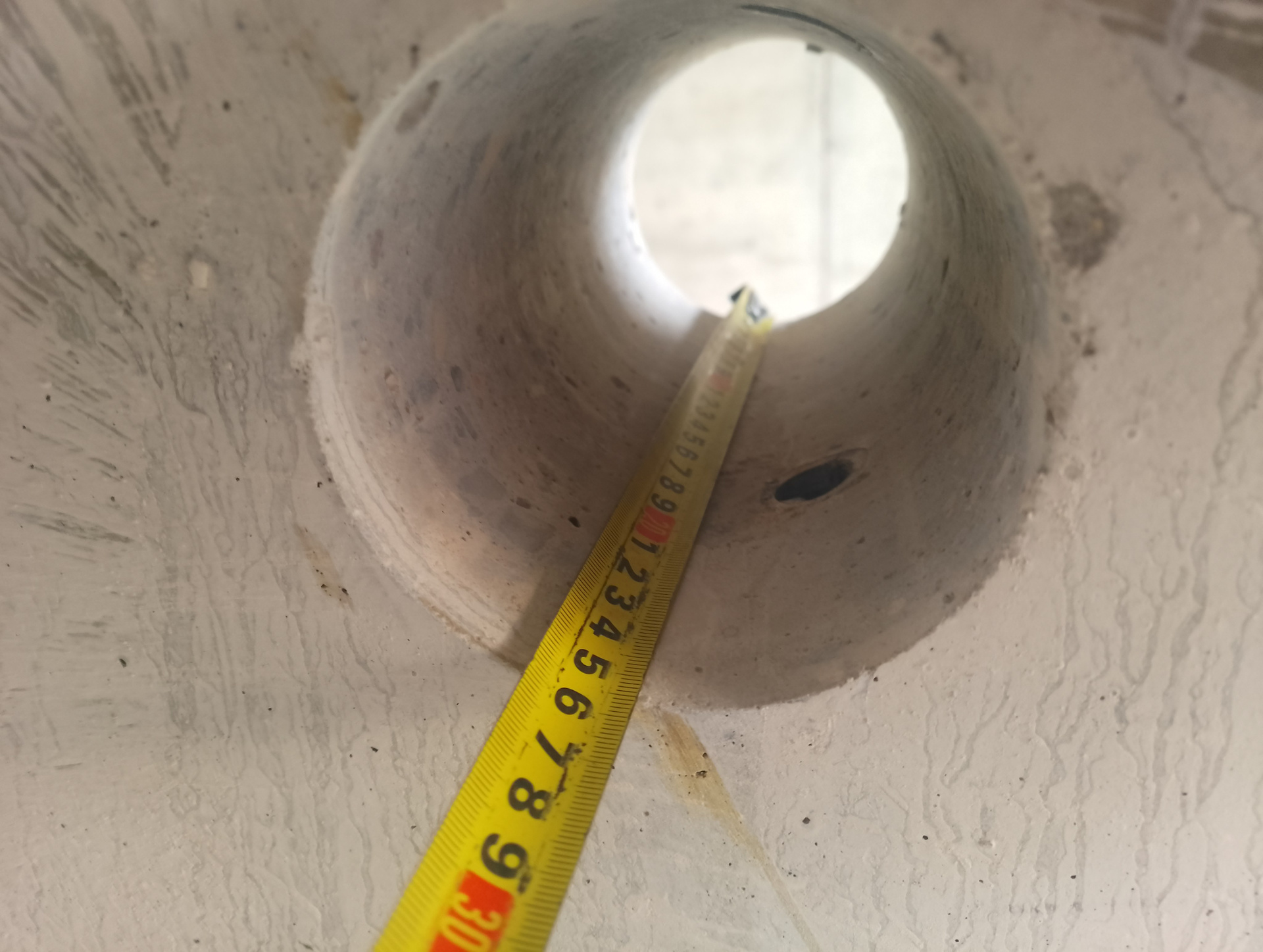
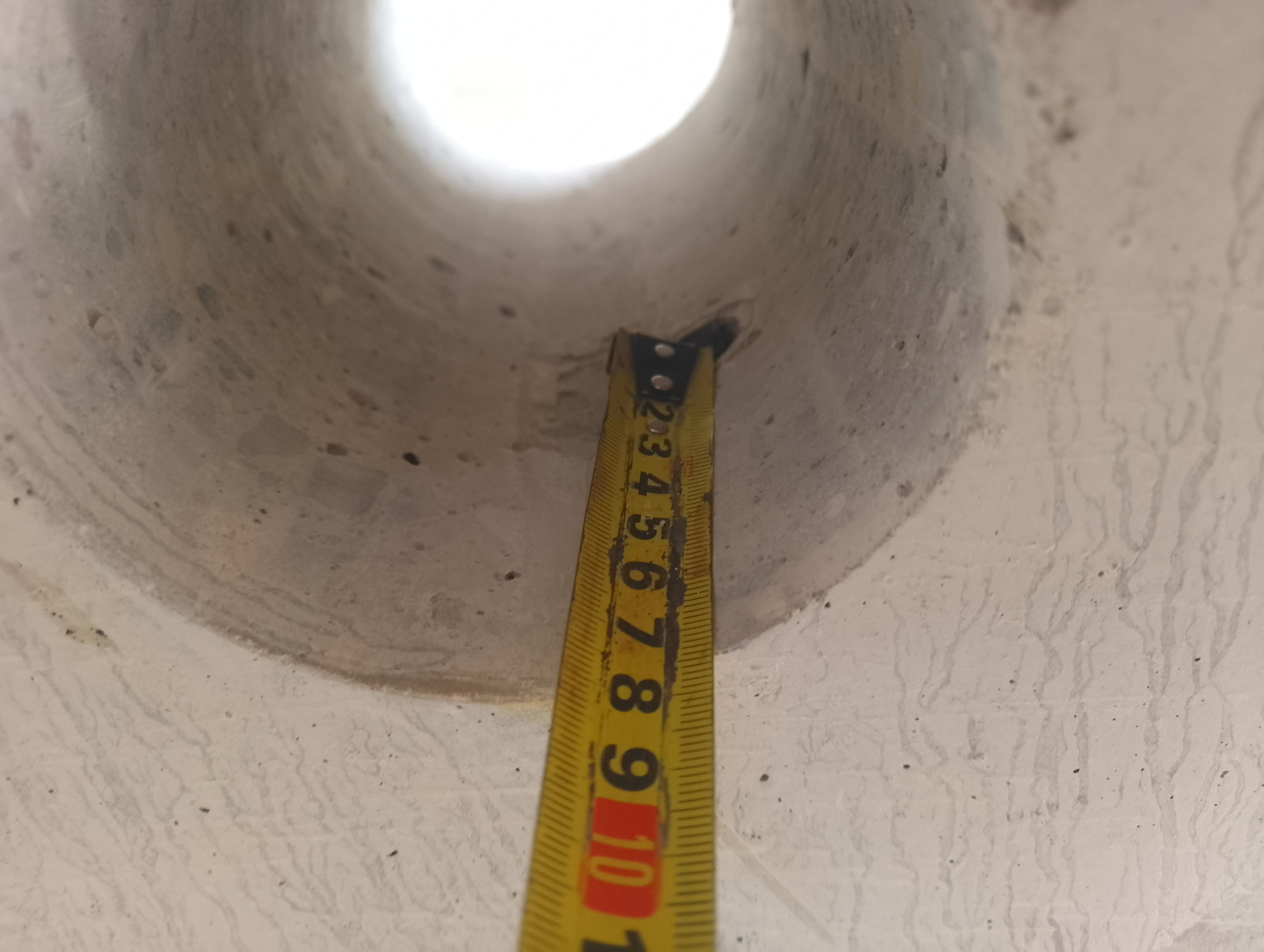
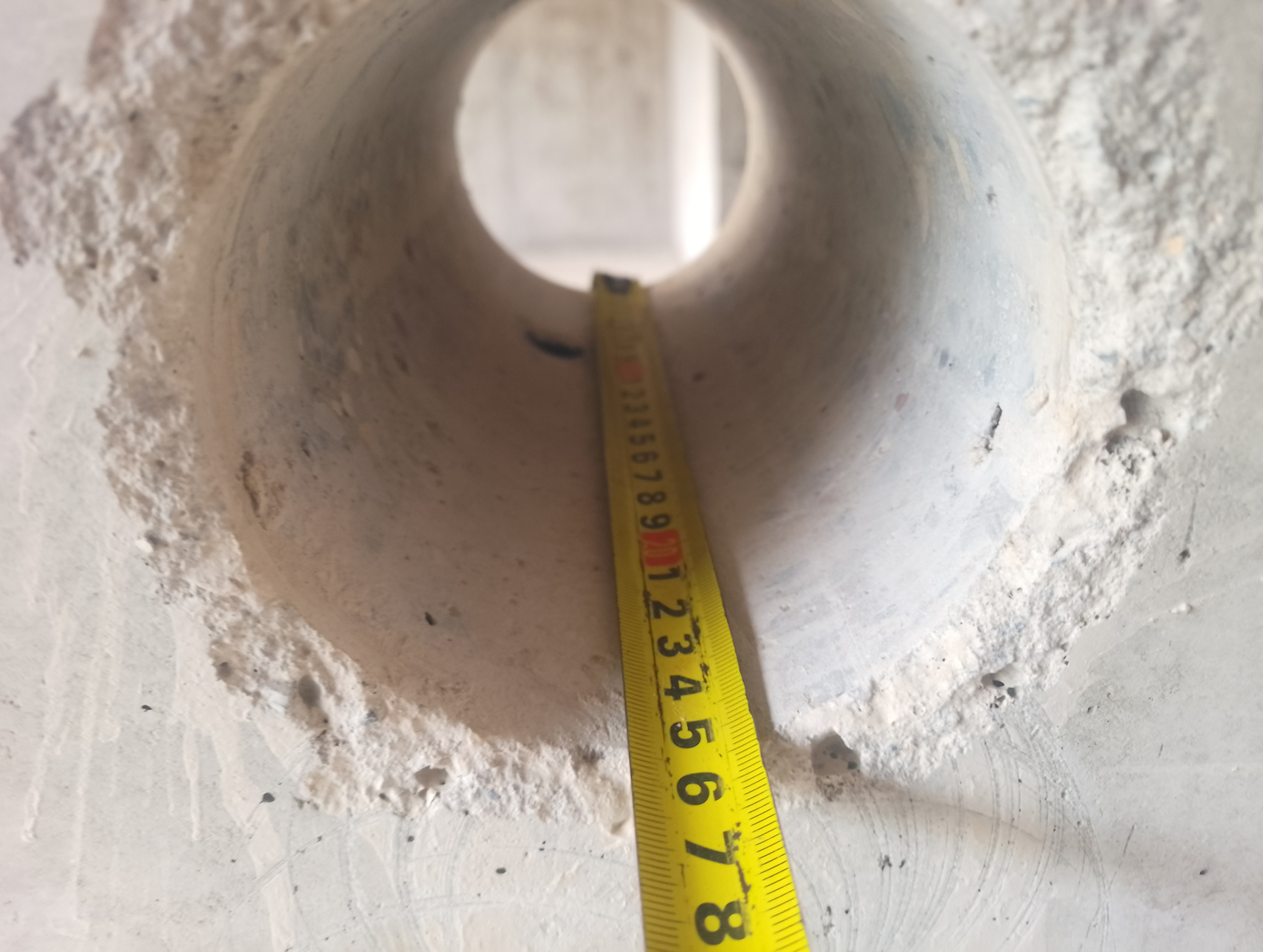
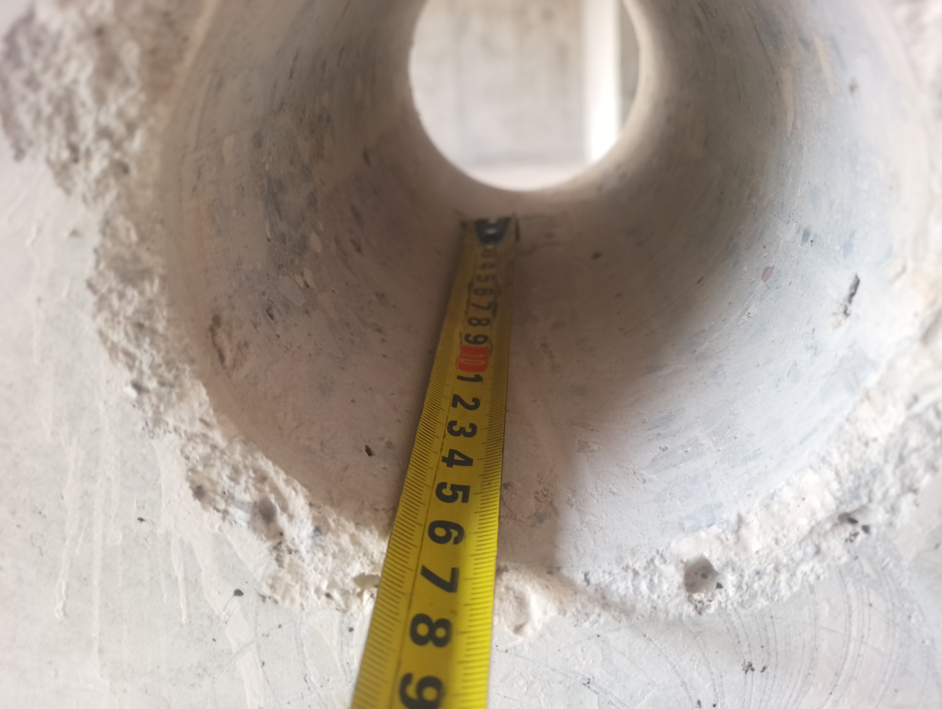
— A cylindrical reflector (plastic tube) with a diameter of 15 mm, embedded at a depth of 73 mm within a 250 mm thick monolithic reinforced concrete pier;
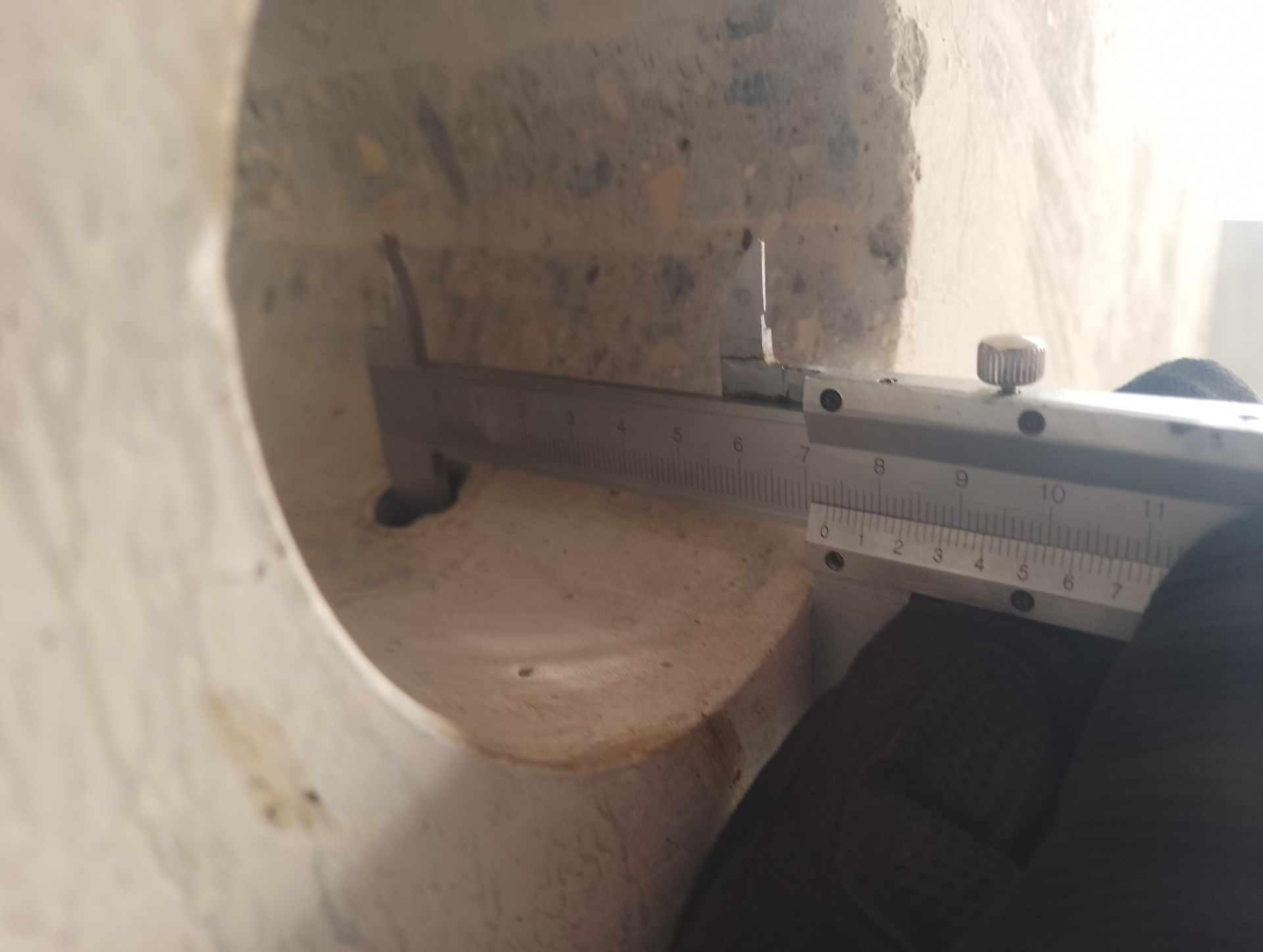
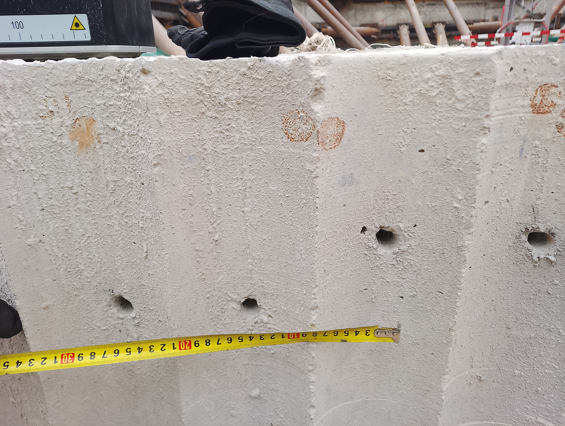
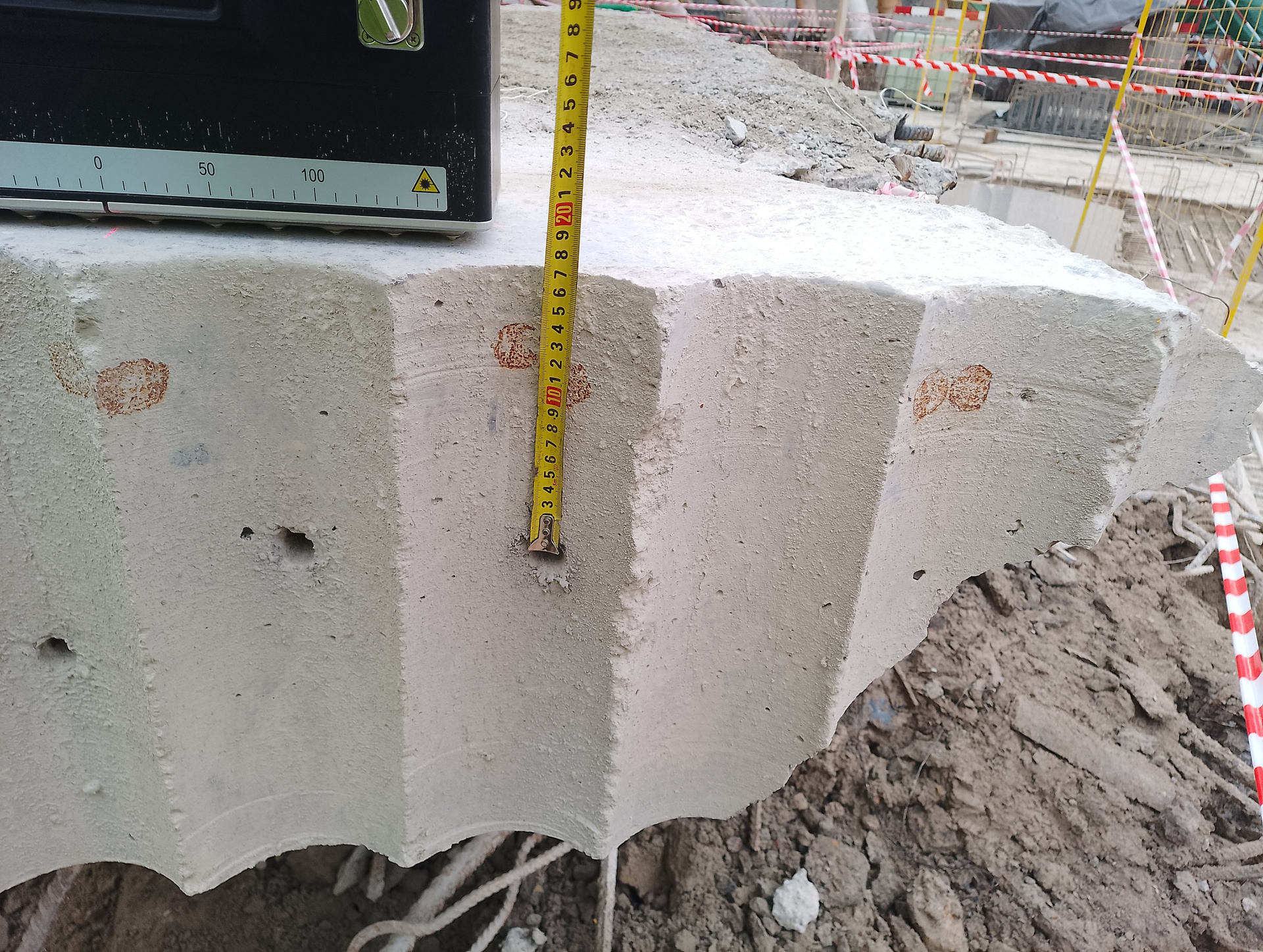
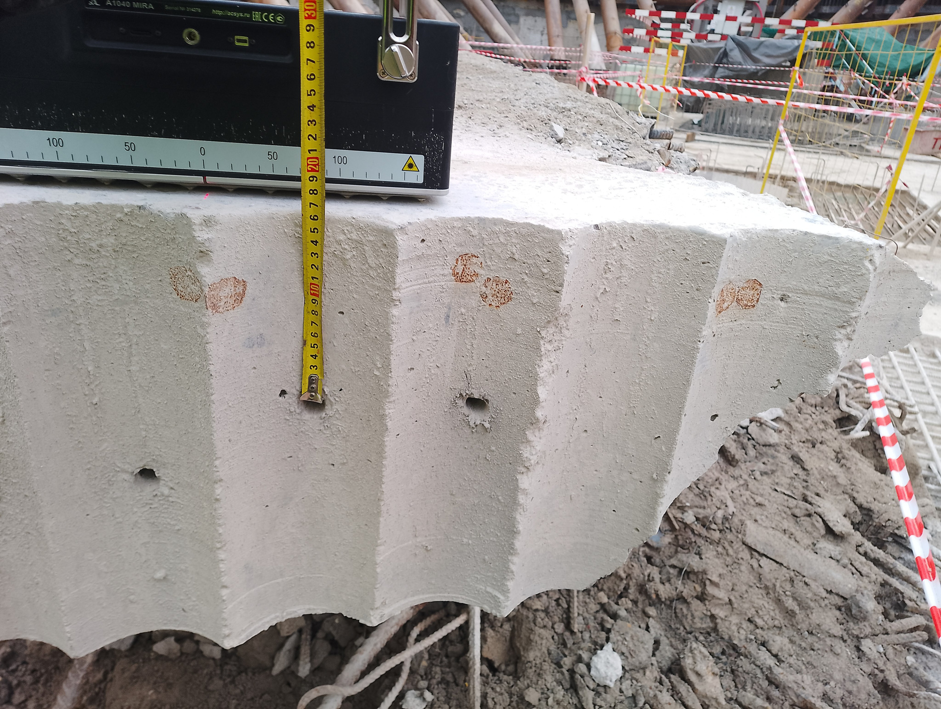
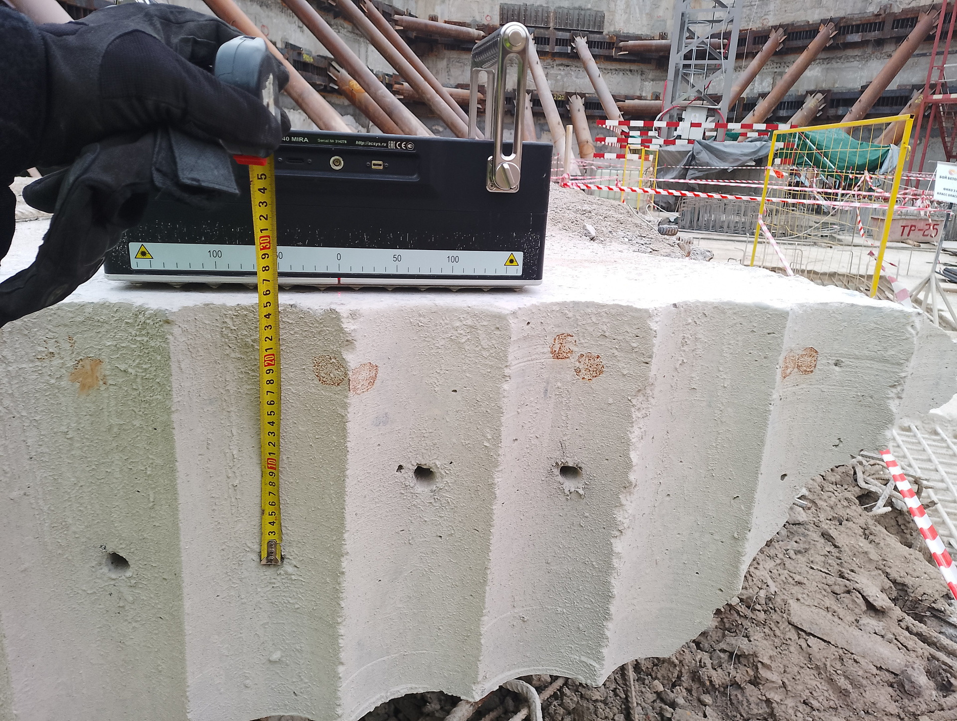
— A 400 mm thick core segment extracted from a foundation slab, containing simulated internal defects (voids). The defect models consist of four drilled holes (16 mm in diameter, 800 mm deep), positioned at depths of approximately 160–170 mm and 230–240 mm below the top surface.
These holes are located both in alignment with reinforcement bars and in the spaces between the bars of the upper reinforcement layer. The top reinforcement of the slab comprises two layers of Ø25 mm AIII rebar spaced at 200 mm intervals.
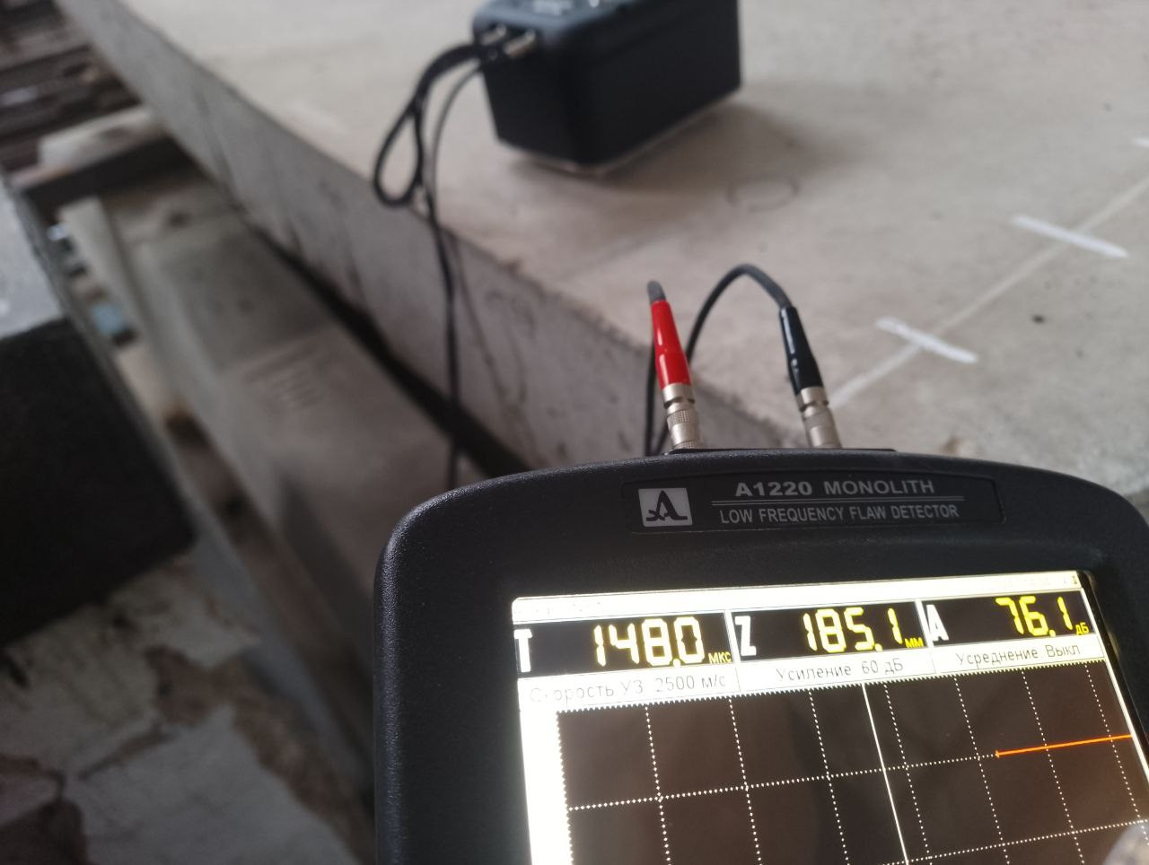
Below are photographs of the pier section showing the extracted core sample containing the embedded cylindrical reflector (15 mm diameter plastic tube) located at a depth of 73 mm. Measurements were performed using the direct transmission method through the borehole.
Below are two B-scan tomograms of the inspected area, acquired using the low-frequency ultrasonic tomograph A1040 MIRA from opposite faces of the pier.
The tomograms clearly reveal the following features:
— Distinct images of vertical reinforcement bars of the structural cage, spaced at 200 mm intervals, with a concrete cover thickness of 70–80 mm;
— A bottom (back-wall) reflection signal at a depth of 250 mm, confirming the full thickness of the pier;
— A well-defined indication of the cylindrical reflector (15 mm diameter plastic tube), with its center located at an approximate depth of 80 mm.
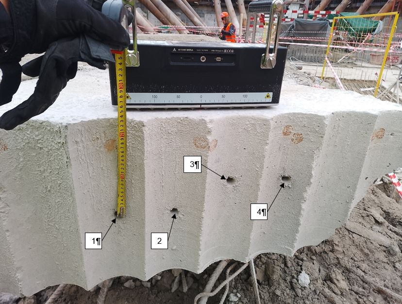
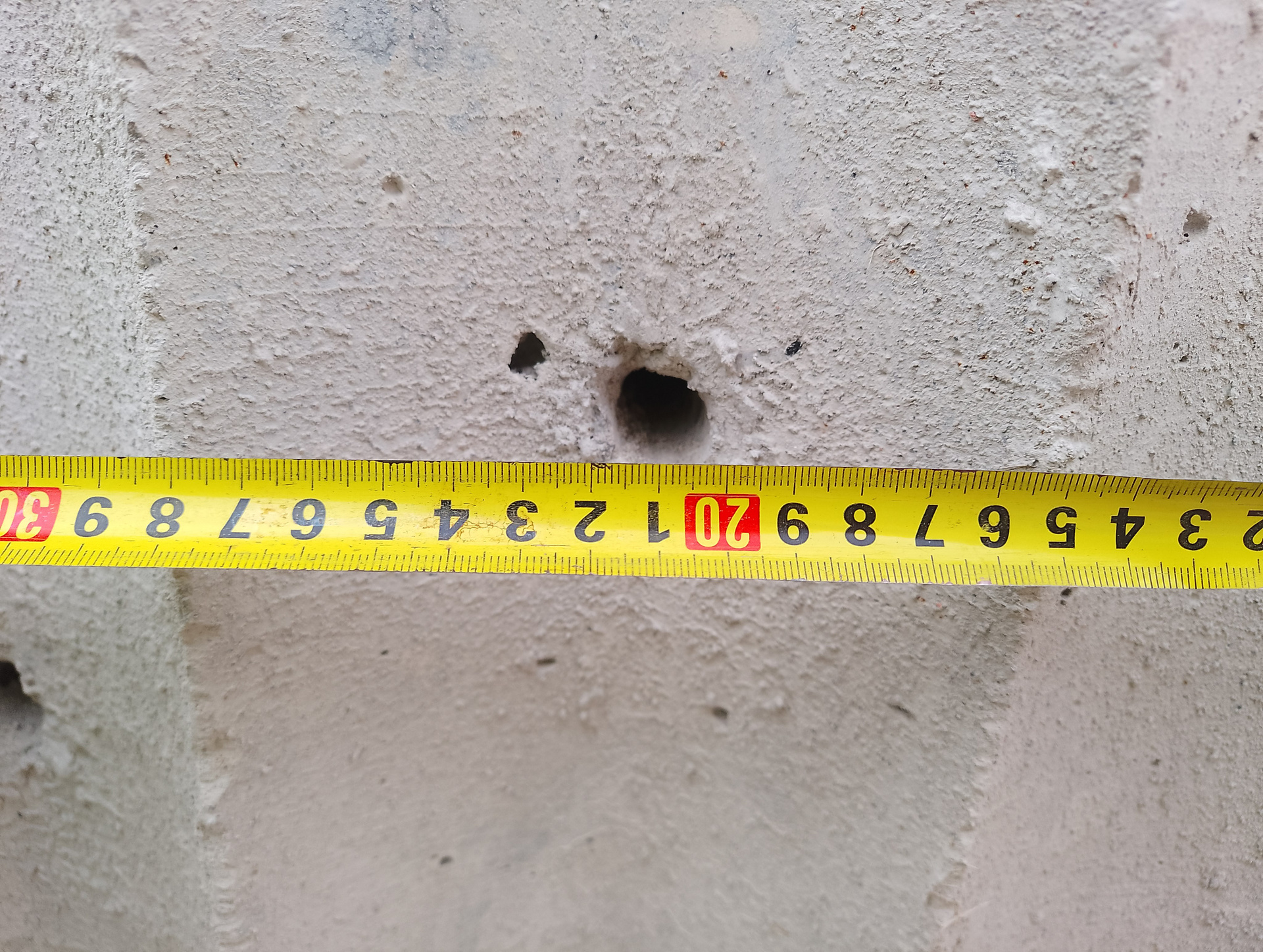
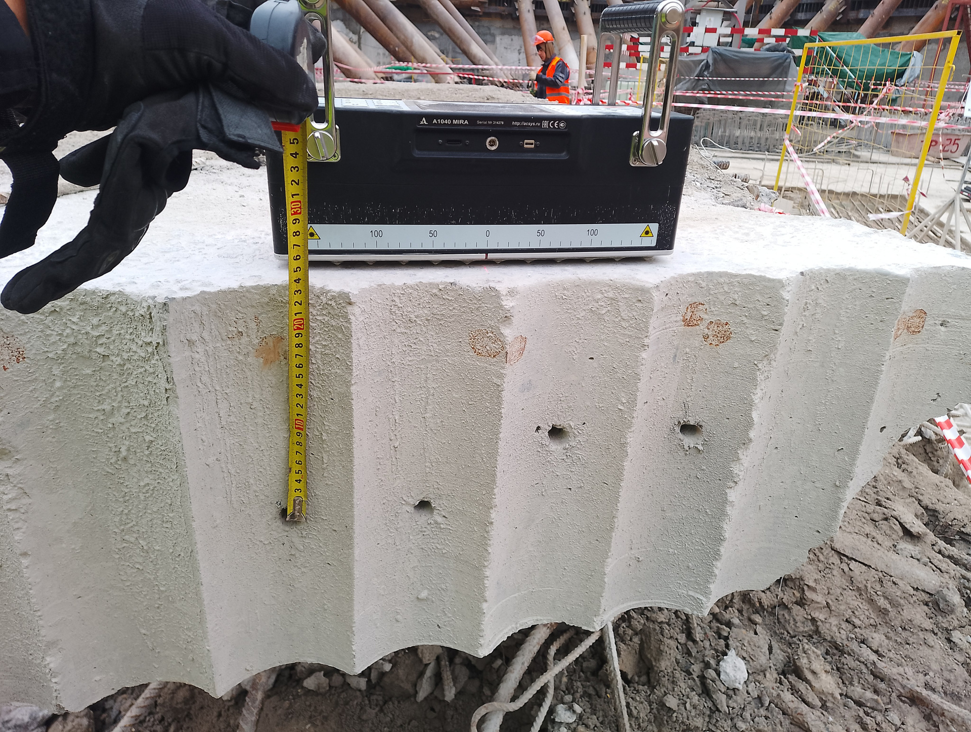
Below are photographs of a 400 mm thick core segment extracted from the body of a foundation slab, containing simulated internal defects (voids). The defect models consist of four boreholes, each 16 mm in diameter and 800 mm deep, positioned at depths of approximately 160–170 mm and 230–240 mm below the top surface. The holes are located both in alignment with the reinforcement bars and in the interstitial spaces between the bars of the upper reinforcement layer. The top reinforcement of the slab comprises two layers of Ø25 mm AIII rebar spaced at 200 mm intervals.
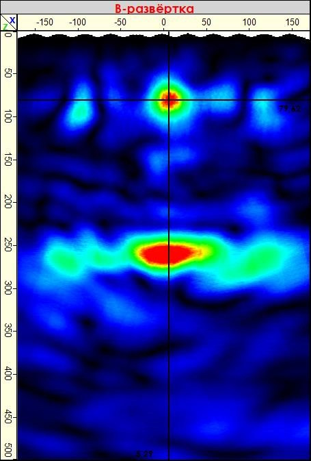
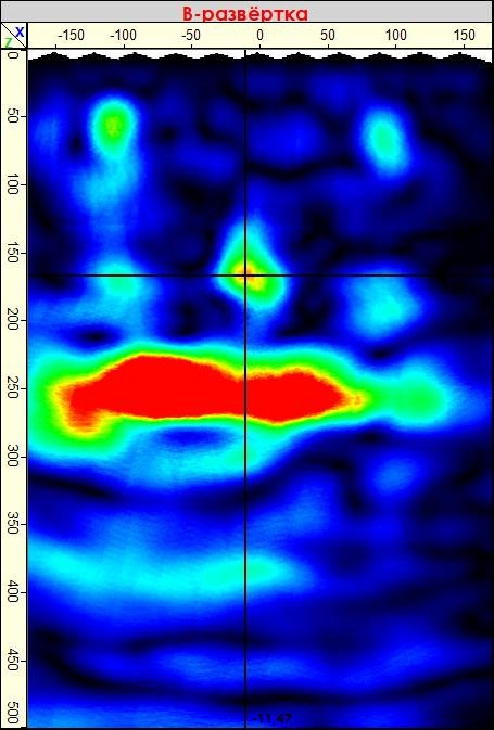
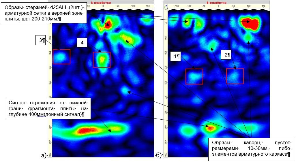
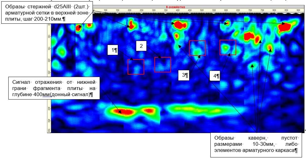
Below are B-scan tomograms of the inspected segment of the foundation slab, obtained using the low-frequency ultrasonic tomograph A1040 MIRA from different faces of the pier.The tomograms clearly show:
— Images of four Ø25 mm AIII reinforcement bars forming the upper reinforcing mesh, spaced at 200–210 mm;
— A bottom (back-wall) reflection signal from the lower boundary of the slab segment at a depth of 400 mm;
— Indications of 16 mm diameter boreholes (simulated defects) No. 1 and No. 2 at a depth of 230–240 mm, highlighted in red boxes;
— Indications of 16 mm diameter boreholes No. 3 and No. 4 at a depth of 160–170 mm, also marked in red boxes.
To request ultrasonic echo tomography services for concrete and reinforced concrete structures or to contact us with questions regarding your specific issue, please fill out the form below, call us, or send a message via any of the messengers listed. If required, we can also arrange site visits anywhere in Russia or around the world! We will do our best to assist you!