

УДК/UDK 620.179.16
A.V. Vysokin (1), lead engineer
S.V. Vysokin (2), engineer
(1) JSC Research Center of Construction (6, 2nd Institutskaya Street, Moscow, 109 428, Russian Federation)
(2) LLC “Tomografiya zhelezobetona” (2, Moskovskikh stroitelei Street, Tuapse, Krasnodar krai, 352 803, Russian Federation)
POSSIBILITIES OF THE ULTRASONIC PULSE-ECHO METHOD IN DETERMINING REINFORCEMENT PARAMETERS OF MONOLITHIC REINFORCED CONCRETE STRUCTURES WITH MULTI-ROW REINFORCEMENT DURING TECHNICAL INSPECTION
Abstract
This article examines the capabilities of the ultrasonic pulse-echo method for determining reinforcement parameters in reinforced concrete structures with multi-row reinforcement during technical condition assessments using domestically produced low-frequency ultrasonic tomographs. The parameters of reinforced concrete structures that can be identified during such inspections are presented. The methodology for determining specific actual parameters of monolithic reinforced concrete structures by means of the ultrasonic echo method is described, along with its capabilities, scope of applicability, and limitations. The paper provides data on the specific features of applying ultrasonic tomographs in the technical inspection of both completed and under-construction monolithic reinforced concrete structures with multi-row reinforcement. Prospects for the use of ultrasonic tomographs across various types of structures are also analyzed.
Keywords: ultrasonic pulse echo; ultrasonic tomograph; reinforced concrete structures; technical inspection; multi-row reinforcement.
Introduction
Reinforced concrete structures are structures made of concrete with working and structural steel reinforcement, in which the design forces from all impacts are perceived by the concrete and the working reinforcement. Reinforced concrete structures with multi-row reinforcement are elements where the reinforcement is arranged in several rows. This can be specified to reduce the size of the structure or improve the mechanical properties of the element. Multi-row reinforcement is considered in the calculation for strength, crack resistance, and deformability of bending, eccentrically compressed, and tensile elements. Reinforcement in several rows occurs in such types of reinforced concrete structures: massive foundation slabs and pile grillages, walls and pylons, beams.
Thus, determining and assessing the actual parameters of the reinforcement system of reinforced concrete structures, which affect the perception of service loads and impacts, as well as the durability of structures, is an important, frequently encountered task solved during technical inspections. The actual parameters of reinforced concrete structures determined during technical inspection serve as initial data for performing verification calculations and developing a project for their restoration or strengthening, and are very important for making informed decisions.
This article examines the capabilities of the ultrasonic pulse-echo method used to determine reinforcement parameters and geometric parameters of reinforced concrete structures with multi-row reinforcement. The methodology is implemented in low-frequency ultrasonic tomographs, the use of which, alone or in combination with other methods for determining reinforcement parameters, is effective in inspecting the technical condition of monolithic reinforced concrete structures with multi-row reinforcement.
Use of the Ultrasonic Pulse-Echo Method in Inspecting the Technical Condition of Monolithic Reinforced Concrete Structures with Multi-Row
Reinforcement Inspection of monolithic concrete and reinforced concrete structures of civil and industrial buildings (structures) to assess their technical condition is carried out in accordance with GOST 31 937-2024. For this purpose, procedures similar to those used in production control of finished reinforced concrete structures are performed, with the difference that during inspection, design, working, and as-built documentation, which significantly simplifies the tasks of inspection, is often unavailable. This creates the need to use not one but several methods for determining the sought actual parameters of the inspected structure, i.e., to solve tasks comprehensively. During the technical inspection of monolithic reinforced concrete structures, depending on the inspection tasks, the following may be determined:
- Actual geometric parameters of structures;
- Actual physical-mechanical parameters of structural materials (reinforcing steel, concrete);
- Parameters of visually detectable defects (cracks, spalls, destruction), quality of the facing surface of monolithic structures;
- Actual parameters of the reinforcement system (type and number of reinforcement layers, reinforcement spacing within a layer, concrete cover thickness, and diameters of reinforcing bars).
Clause 5.3.1.10 of GOST 31 937-2024 lists methods for determining parameters of actual reinforcement of finished reinforced concrete structures used during technical inspection:
- Performing test openings with exposure of reinforcement for direct determination of reinforcement parameters using manual measuring tools (calipers, depth gauges, rulers, tape measures);
- Magnetic method according to GOST 22 904-2023 “Reinforced Concrete Structures. Magnetic Method for Determining Thickness of Concrete Cover and Location of Reinforcement”;
- Radiation method according to GOST 17 625-83 “Reinforced Concrete Structures and Products. Radiation Method for Determining Thickness of Concrete Cover, Dimensions and Location of Reinforcement.”
Furthermore, for determining the reinforcement system of reinforced concrete structures, the standard permits the use of geophysical (ground-penetrating radar) methods and the ultrasonic method. In most cases, when determining parameters of the reinforcement system of elements of reinforced concrete structures of civil, public, and industrial buildings, for solving inspection tasks, the application of the magnetic method and performing test openings with exposure of reinforcement for direct determination of parameters using manual measuring tools is technically and economically justified and sufficient.
However, the constant complication of volumetric-planning and structural solutions in newly designed and constructed buildings forces the reinforcement system of reinforced concrete frame elements to become more complex. To enable cross-sections of reinforced concrete structure elements to withstand the colossal forces arising from service loads in modern buildings, it is constantly necessary to increase the cross-sectional dimensions, physical-mechanical characteristics of concrete and reinforcing steel, and often complicate the reinforcement system, including placing reinforcement in several (two, three, or more) rows. Using the magnetic method or the method of direct openings in such structures will be ineffective or impossible.
Also, existing methods for determining reinforcement parameters of reinforced concrete structures turn out to be limited in applicability or inapplicable in cases of:
- Deep location of reinforcement cage bars (more than 100mm);
- Dense arrangement of reinforcement cage bars (less than 100mm), in areas of bar overlap; · Installation of anti-spalling meshes;
- Need to determine reinforcement parameters of a structure with one-sided access (in embedded, underground structures);
- Need to determine reinforcement parameters of a structure with one-sided access (in vertical structures located along the perimeter of floor slabs, high-rise buildings);
- Use of permanent formwork;
- Inability to perform test openings of the concrete cover.
The ultrasonic pulse-echo method allows effective determination of individual reinforcement parameters (number of reinforcement rows, coordinates of centers and spacing of reinforcing bars) of the second, third, and subsequent rows of reinforcement located at different depths in various types of structures. Among the limitations of the ultrasonic pulse-echo method, the inability to determine diameters of reinforcement cage elements should be noted.
Below, in the following examples, results from inspecting fragments of reinforced concrete structures with multi-row reinforcement are presented.
Example 1. Use of the Ultrasonic Pulse-Echo Method in Inspecting the Technical Condition of a Fragment of a Monolithic Reinforced Concrete Wall with Multi-Row Reinforcement
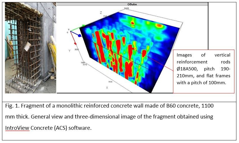
This example considers the results of inspecting a wall fragment 1100 mm thick, made of high-strength monolithic concrete. Concrete of walls is compressive strength class B60, SУБ — self-compacting concrete mixture. Wall reinforcement was done with spatial reinforcement blocks assembled from flat frames.
Vertical reinforcement of frames — Ø18A500. Horizontal reinforcement — Ø18A500, spacing 200 mm. According to design documentation requirements, delaminations, voids, and cracks are not permitted in the concrete of structures.
The goals of the inspection were to determine the presence of hidden defects in the internal structure of the concrete (including cavities, areas of insufficiently compacted and delaminated concrete, foreign inclusions), determine and assess actual reinforcement parameters of the walls (spacing of vertical and horizontal reinforcement bars of spatial frames (reinforcement blocks), cover thickness), determine wall thickness in areas with one-sided access. Performing test openings for these structures was not allowed.
Application of the magnetic method according to GOST 22 904-2023 allowed obtaining values for cover thickness and bar spacing for the first row of reinforcement.
Using the low-frequency ultrasonic tomograph A1040MIRA (ACS) allowed obtaining data on the actual reinforcement parameters of the structure in deeper rows.
Fig. 1. Fragment of a monolithic reinforced concrete wall made of B60 concrete, 1100 mm thick. General view and three-dimensional image of the fragment obtained using IntroView Concrete (ACS) software.
Fig. 2. Fragment of a monolithic reinforced concrete wall made of B60 concrete, 1100 mm thick. B, C, D-scans and three-dimensional image of the fragment obtained using IntroView Concrete (ACS) software.
Fig. 3. Fragment of a monolithic reinforced concrete wall made of B60 concrete, 1100 mm thick. B-scans
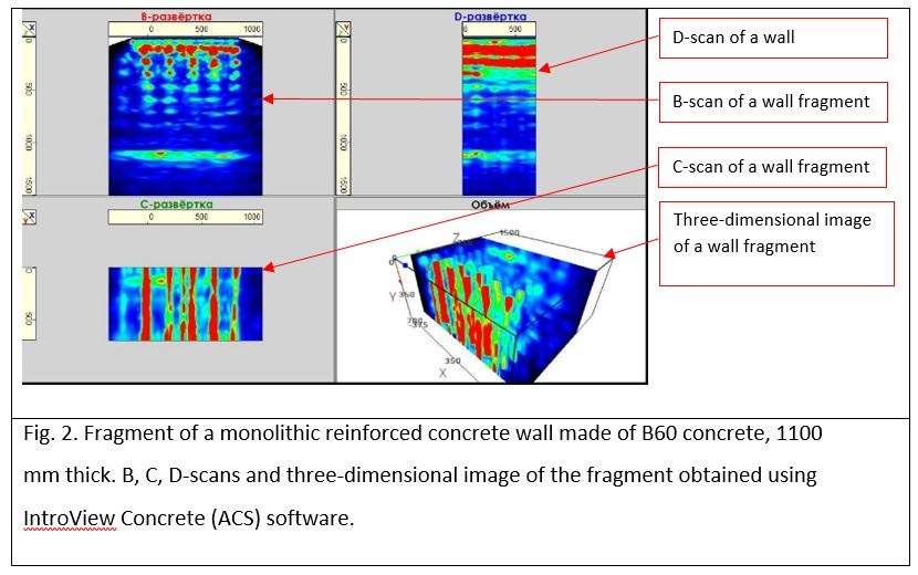
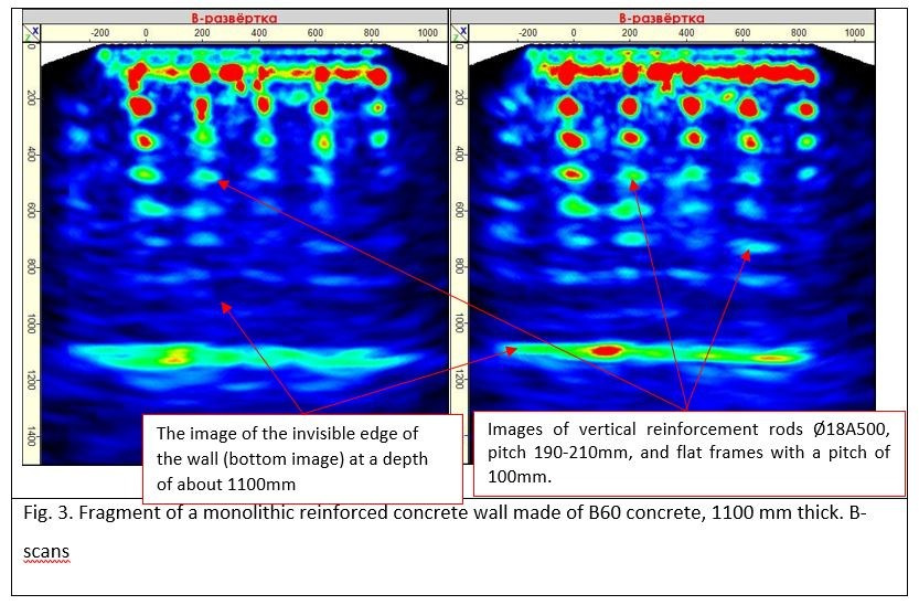
Based on the analysis of tomograms, the following conclusions can be drawn:
- B-scans reveal images of vertical reinforcement of flat frames (7 rows), bar spacing within a frame — 100 mm, frame spacing — 200 mm. Actual distance to the centers of vertical reinforcement bars of the 1st row — 100 mm;
- Individual (weakened) images of fragments of vertical reinforcement of the 8th row of flat frames were identified;
- No defects in the internal structure of concrete with linear dimensions exceeding 16 mm were detected;
- Actual thickness of the wall structures is 1100 mm.
Example 2. Use of the Ultrasonic Pulse-Echo Method in Inspecting the Technical Condition of a Fragment of a Monolithic Reinforced Concrete Beam with Multi-Row Arrangement of Transverse Reinforcement Frames.
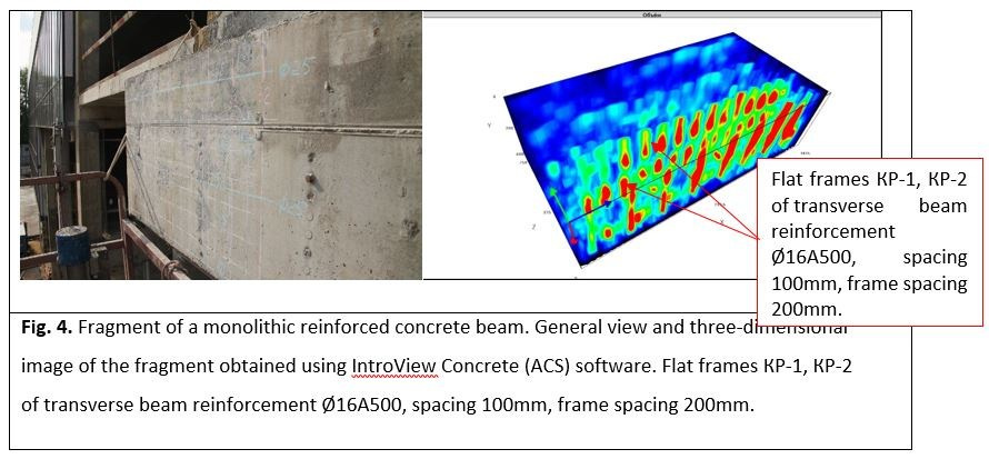
This example considers the results of inspecting a fragment of a cantilever beam 600 mm thick, made of monolithic concrete. Concrete of the beam is compressive strength class В40. Beam reinforcement was done with spatial reinforcement blocks assembled from flat frames.
Vertical reinforcement of frames — Ø18A500. Horizontal reinforcement — Ø18A500, spacing 200 mm. According to design documentation requirements, delaminations, voids, and cracks are not permitted in the concrete of structures.
The goals of the inspection were to determine the presence of hidden defects in the internal structure of the concrete (including cavities, areas of insufficiently compacted and delaminated concrete, foreign inclusions), determine and assess actual reinforcement parameters of the walls (spacing of vertical and horizontal reinforcement bars of spatial frames (reinforcement blocks), cover thickness), determine thickness on sections with one-sided access.
Performing test openings for these structures was not allowed. Application of the magnetic method according to GOST 22 904-2023 allowed obtaining values for cover thickness and bar spacing for the first row of reinforcement.
Using the low-frequency ultrasonic tomograph A1040MIRA (ACS) allowed obtaining data on the actual reinforcement parameters of the structure in deeper rows.
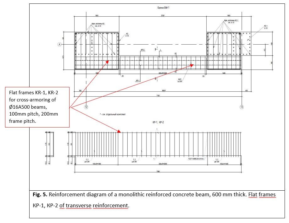
Fig. 4. Fragment of a monolithic reinforced concrete beam. General view and three-dimensional image of the fragment obtained using IntroView Concrete (ACS) software. Flat frames КР-1, КР-2 of transverse beam reinforcement Ø16A500, spacing 100mm, frame spacing 200mm.
Fig. 5. Reinforcement diagram of a monolithic reinforced concrete beam, 600 mm thick. Flat frames КР-1, КР-2 of transverse reinforcement.
Fig. 6. Fragment of a monolithic reinforced concrete beam, 600 mm thick. B-scan and Section of the three-dimensional image of the fragment.
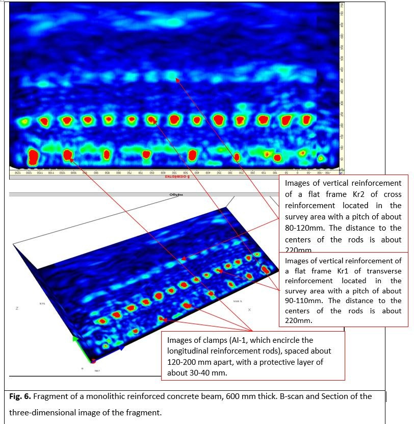
Based on the analysis of tomograms, the following conclusions can be drawn:
- B-scans reveal individual images of longitudinal reinforcement bars (Pos.1);
- B-scans reveal images of stirrups (pos. АИ-1, enveloping longitudinal reinforcement bars) spaced approximately 120-200mm apart, cover thickness approximately 26-38mm;
- B-scans reveal images of vertical reinforcement of flat frame Кр1 of transverse reinforcement, located in the inspection area with spacing approximately 90-110mm;
- B-scans reveal individual images of vertical reinforcement of flat frame Кр2 of transverse reinforcement, located in the inspection area with spacing approximately 80-120mm;
- No defects in the internal structure of concrete with linear dimensions exceeding 20mm were detected in the beam structure within the inspection zone.
Conclusion
Positive experience in using low-frequency ultrasonic tomographs and the considered examples of applying the ultrasonic pulse-echo method to determine parameters of the reinforcement system of monolithic reinforced concrete structures with arrangement of reinforcement cage elements in several rows, testify to the possibility of its effective application as a tool for solving production tasks alone or in combination with other methods.


