Visual and Instrumental Inspection of Monolithic Reinforced Concrete Columns
The purpose of conducting the technical condition inspection of vertical monolithic reinforced concrete columns in accessible areas is to determine their actual technical condition with conclusions regarding the presence of defects in the internal concrete structure.
The inspection objectives were:
—collection and analysis of design-technical, as-built, and survey documentation;
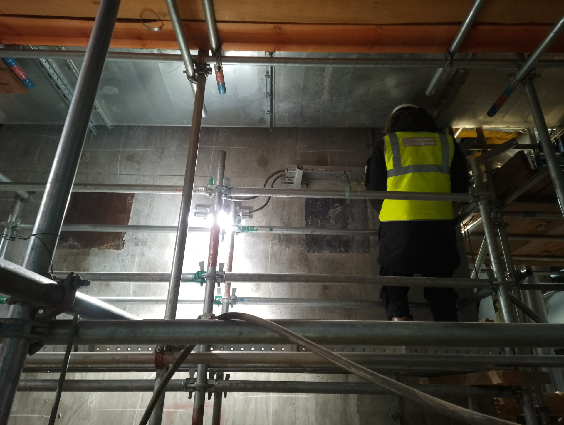
—comprehensive visual inspection and non-destructive testing of monolithic reinforced concrete column structures in accessible areas;
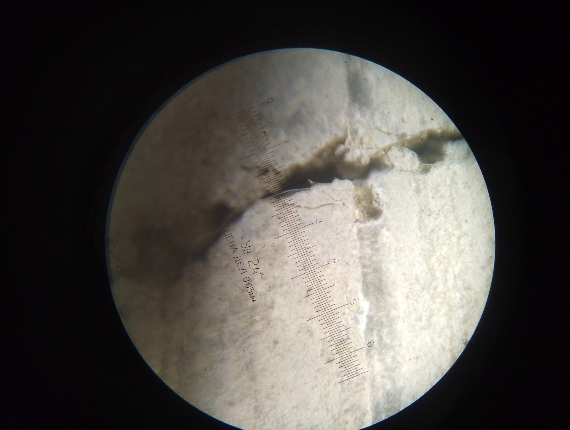
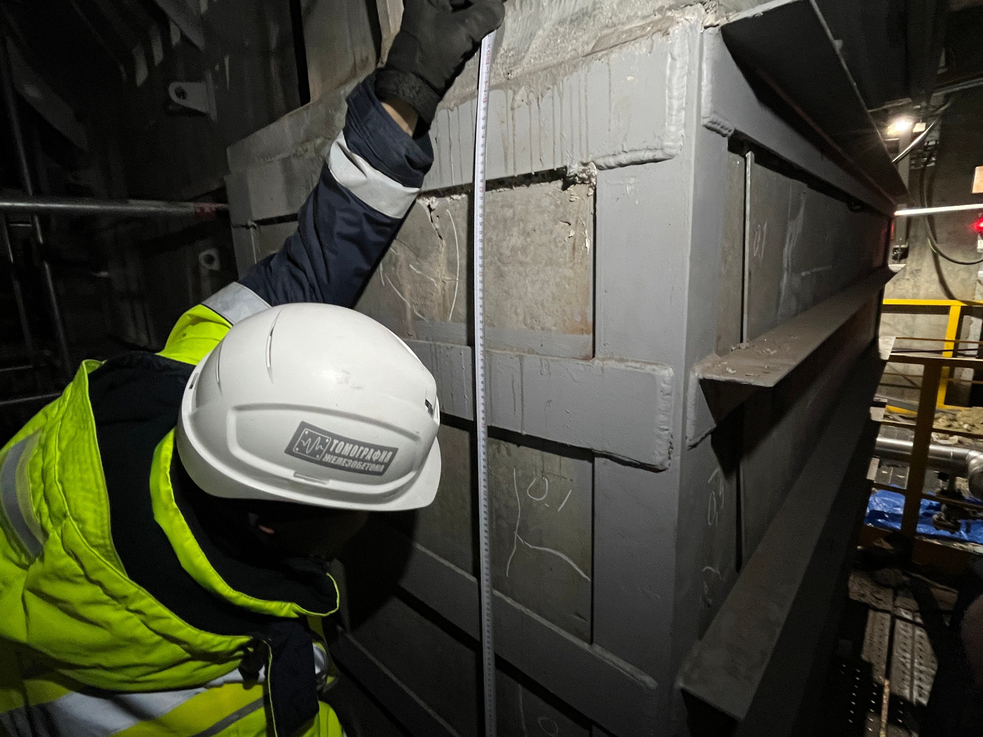
—instrumental inspection and determination of parameters of visually identified defects in monolithic reinforced concrete columns, photography;
—dimensional survey work to the extent necessary to achieve inspection objectives;
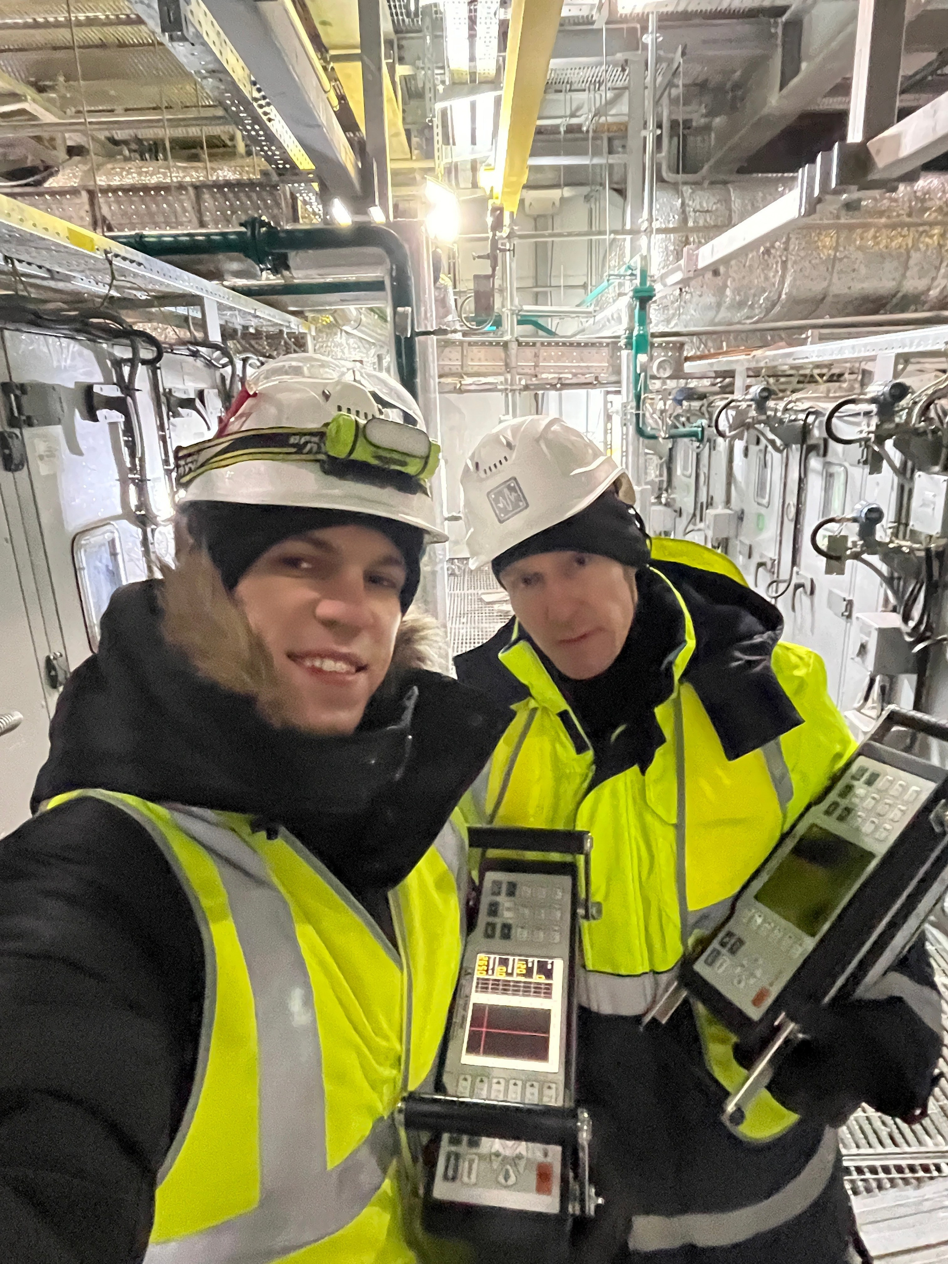
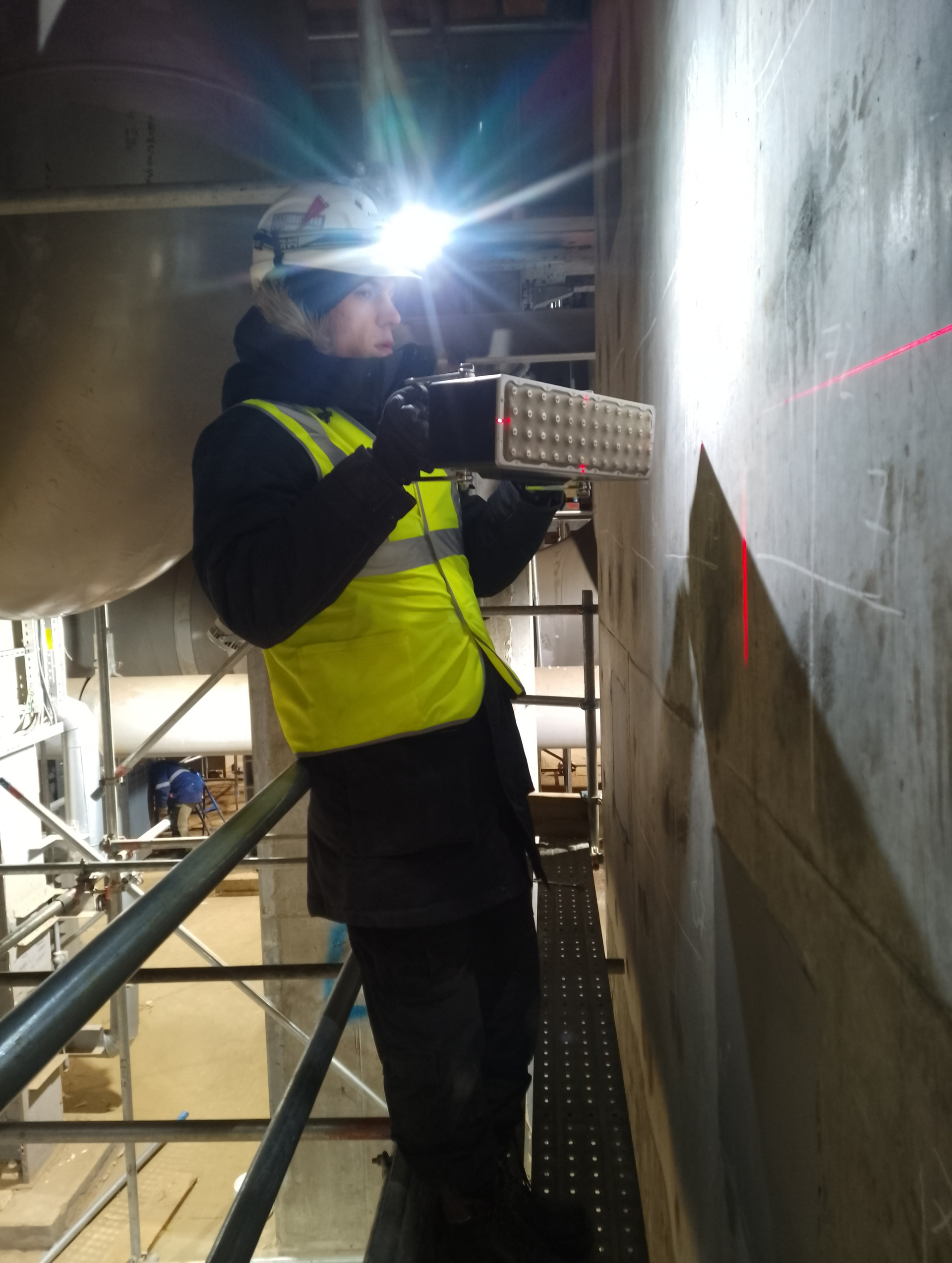
—determination of the presence of defects in the internal concrete structure of monolithic reinforced concrete columns using the ultrasonic pulse-echo method (with the low-frequency ultrasonic tomograph A1040 MIRA);
—dentification and analysis of defect causes;
—development of recommendations for eliminating identified defects and damages;
—preparation of a conclusion based on technical inspection results.
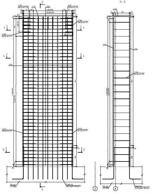
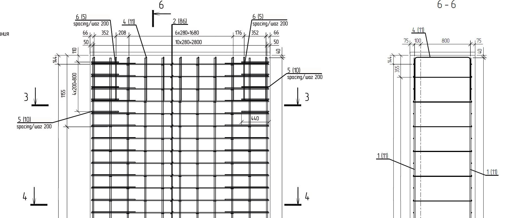
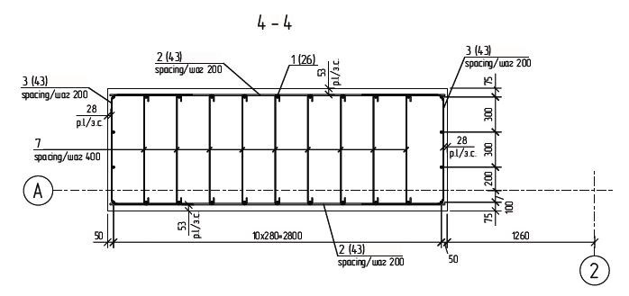
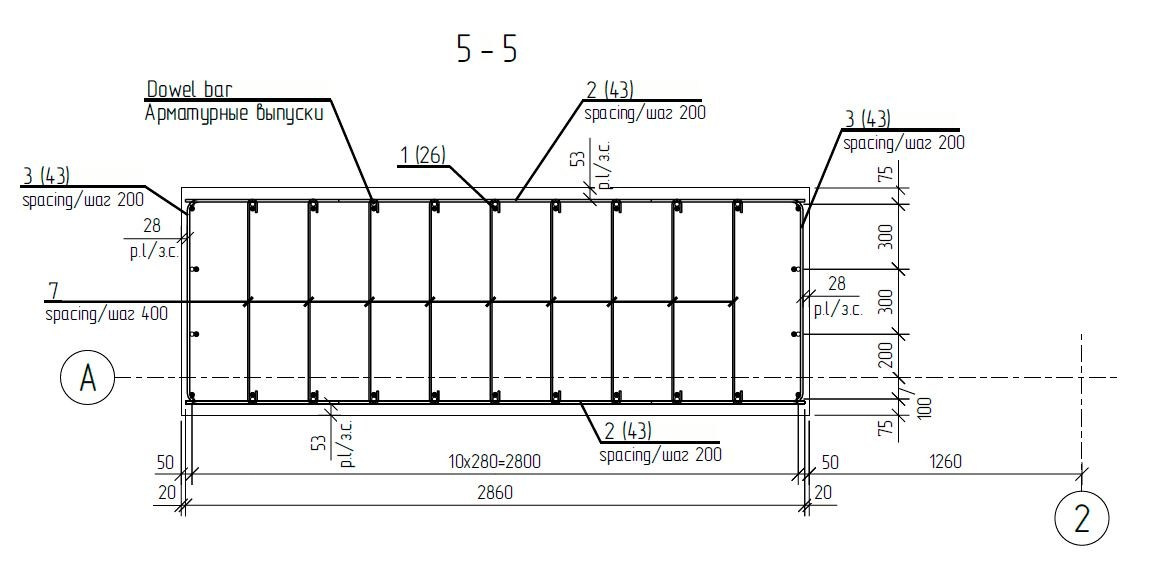
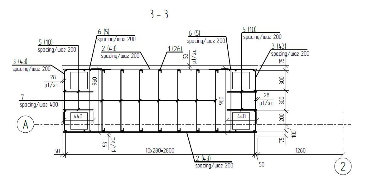
Below are presented fragments of the Working Documentation, Section KR (reinforcement schemes of monolithic reinforced concrete columns).
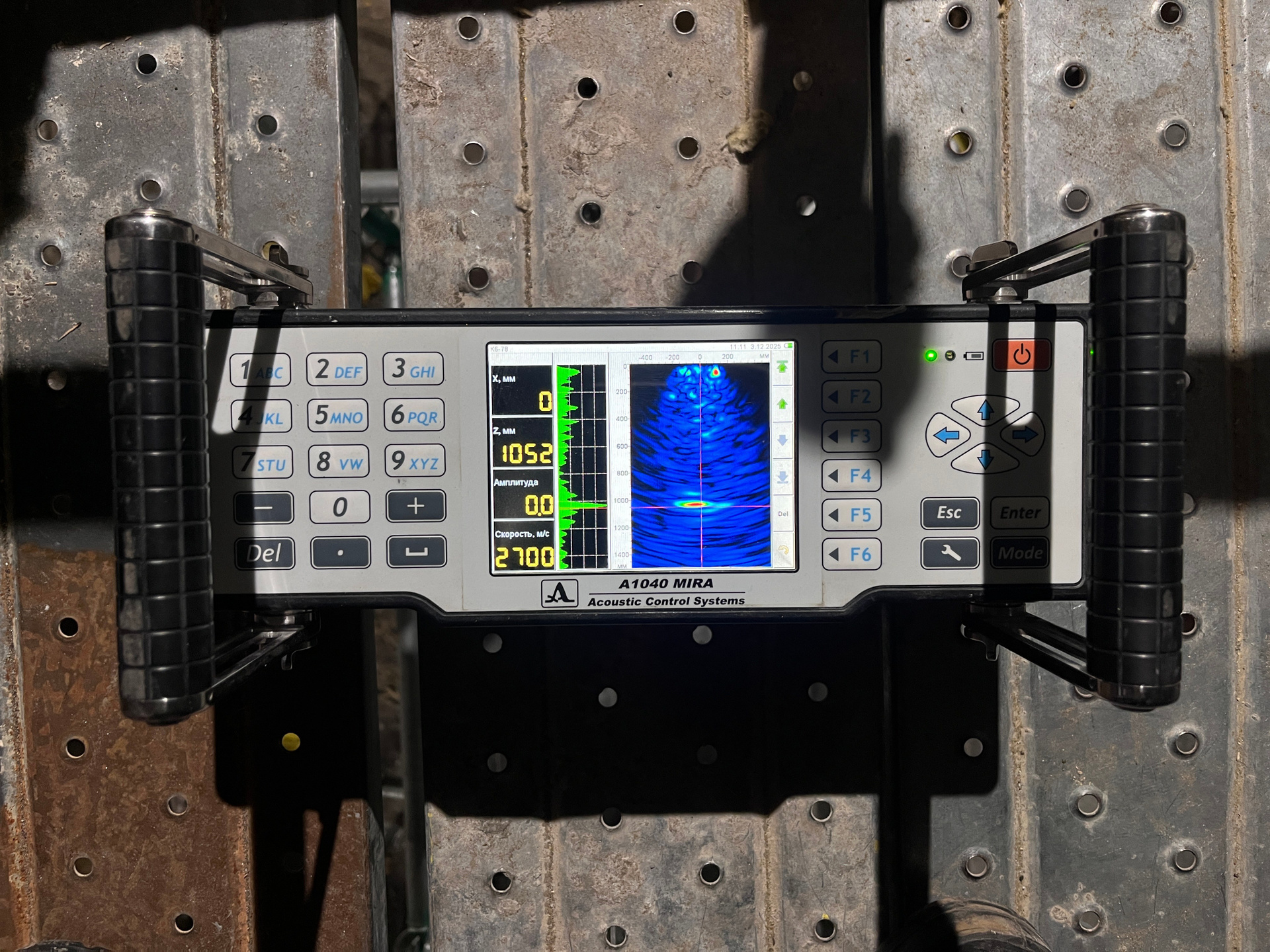
Conclusions Based on the Results of Internal Concrete Structure Inspection of Monolithic Reinforced Concrete Columns by Ultrasonic Pulse-Echo Method (Using Low-Frequency Ultrasonic Tomograph A1040 MIRA)
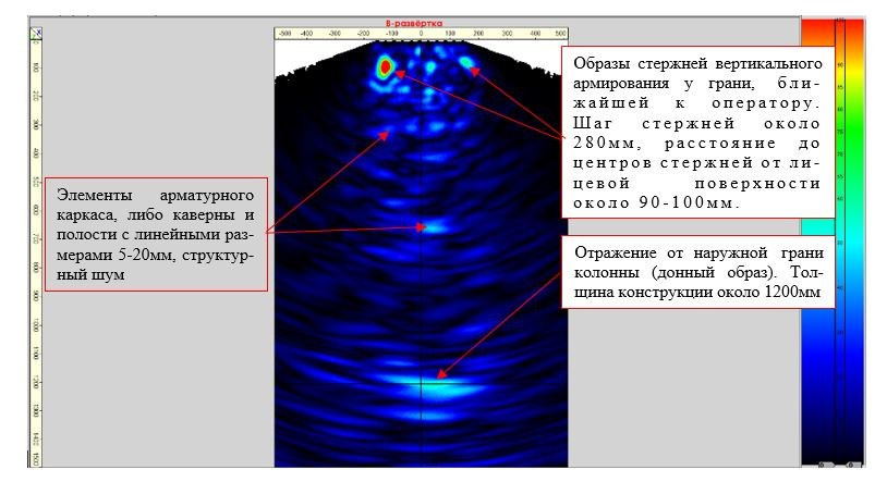
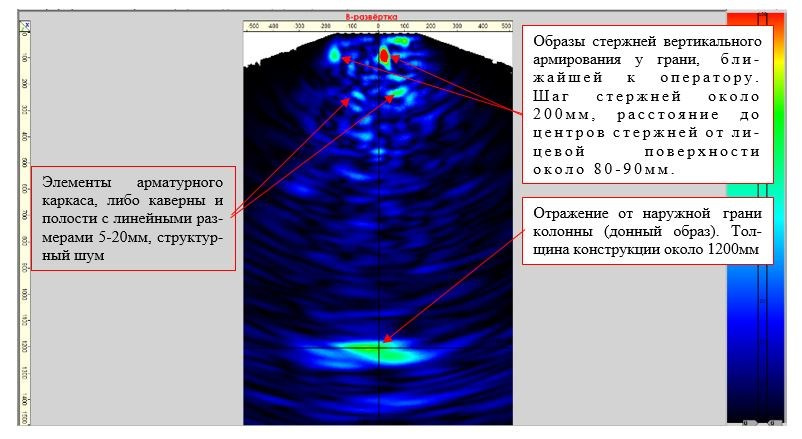
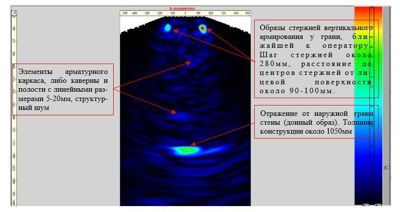
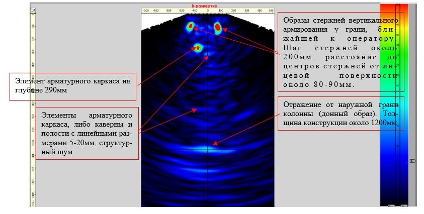
The actual thickness of column structures was 1050 and 1200 mm, respectively. To obtain information about the internal concrete structure of column structures, their inspection was performed using ultrasonic tomographs A1040 Mira (manufacturer: LLC “Acoustic Control Systems”). Inspection was carried out on individual sections of column structures, evenly distributed with a regular spacing of 500 mm along the length and height of the structures.
When anomalous areas were detected, the scanning step was reduced for more detailed study and localization of the anomaly. Scanning with the tomograph was performed on two opposite faces of column structures with horizontal and vertical positioning of the instrument’s antenna array at each section.
When the tomograph was positioned horizontally, the operator obtained information about vertical reinforcement parameters at the section (vertical reinforcement spacing, concrete cover thickness), compared the obtained data with the design reinforcement data contained in the Working Documentation materials, and made conclusions about the possible presence of internal concrete structure defects (voids, areas of insufficiently compacted or delaminated concrete, foreign objects) when anomalous areas were detected in zones atypical for the reinforcement system.
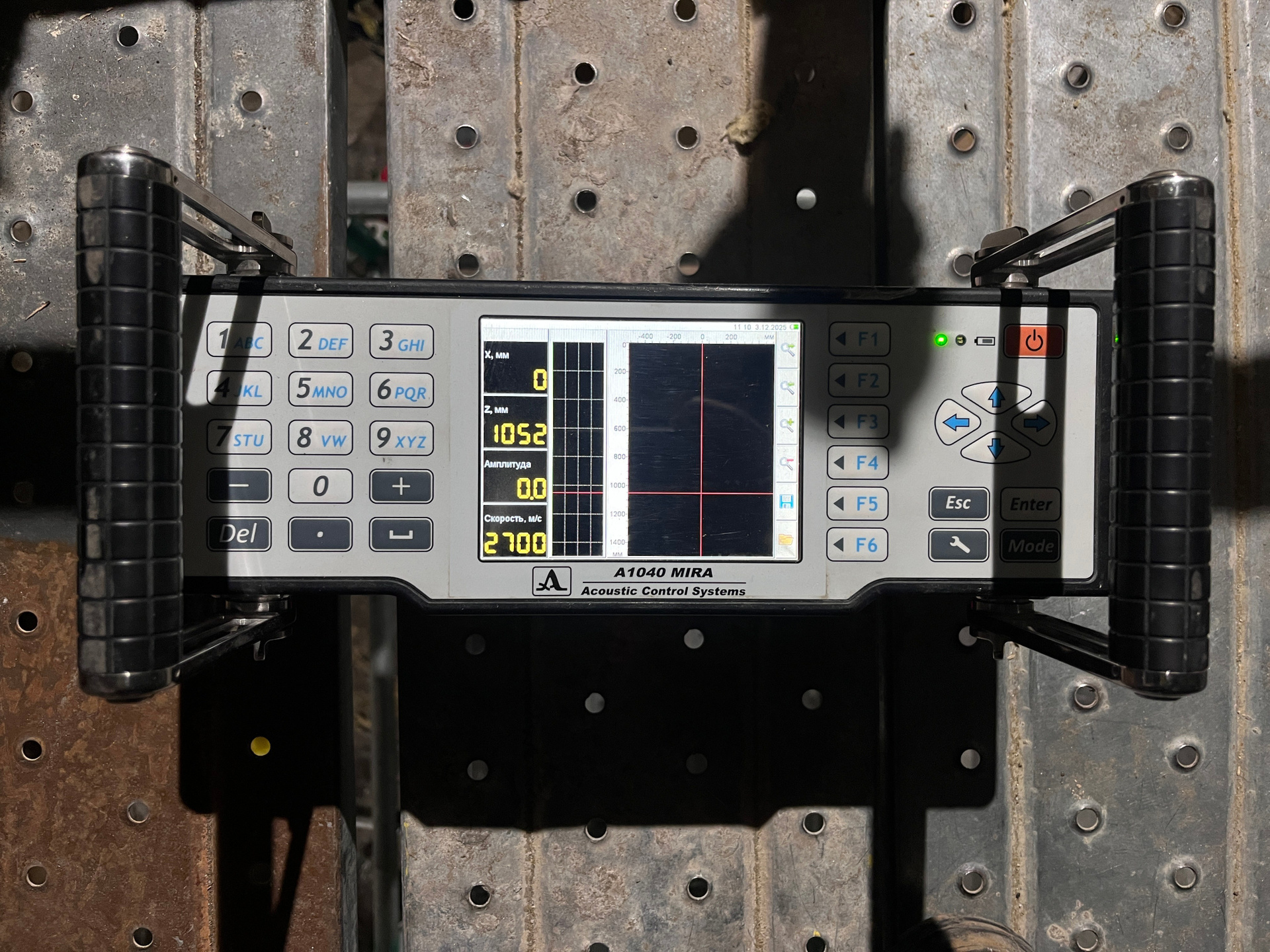
When the tomograph was positioned vertically, the operator obtained information about horizontal reinforcement parameters and performed analysis of the obtained data. Scanning results were presented as individual B-scans (tomograms), on which images of vertical and horizontal reinforcement near the operator’s face (areas of bright red, yellow colors) and the bottom image (image of the opposite face of the structure) were detected. Individual highlights (groups of highlights) of light green color represent images of cavities with linear dimensions of approximately 10-20 mm, or images of column reinforcement cage elements.
In the areas inspected by the ultrasonic pulse-echo method, no defects of the internal concrete structure (cavities, voids, fragments of foreign objects, etc.) with linear dimensions exceeding 20 mm were detected. Below are individual B-scans with horizontal and vertical positioning of the tomograph’s antenna array with explanations.